Appendix BSpecifications
152
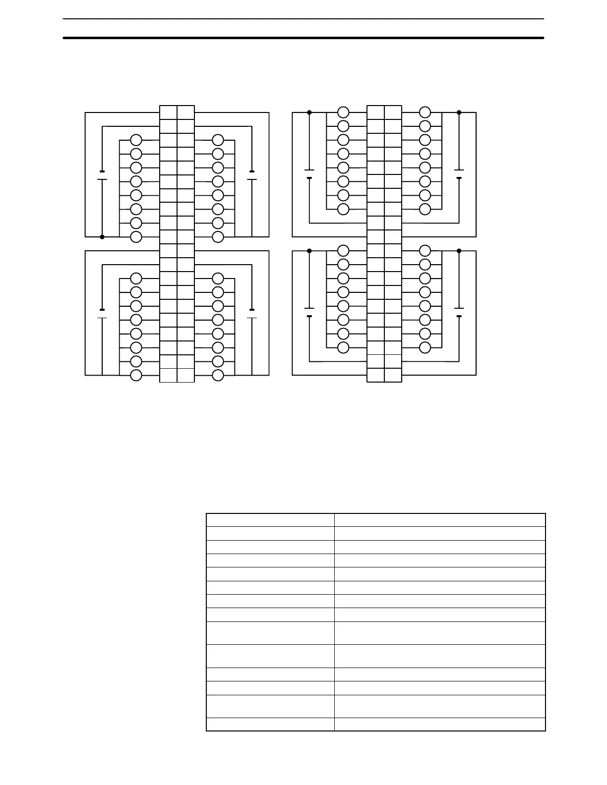
Terminal Connections
I/O word “m”I/O word “m+1”
CN1
I/O word “m+3”I/O word “m+2”
CN2
L
L
1
0
B
1
2
2
3
3
4
4
5
5
6
6
7
7
8
9
0
1
2
3
4
5
6
7
COM
A
+
COM
+
10
11
12
13
14
15
16
18
19
20
17
8
9
10
11
12
13
14
15
COM
+
8
9
10
11
12
13
14
15
COM
+
1
2
3
4
5
6
7
8
9
10
11
12
13
14
15
16
18
19
20
17
L
L
L
L
L
L
L
L
L
L
L
L
L
L
L
L
L
L
L
L
L
L
L
L
L
L
L
L
L
1L
0
A
1
2
2
3
3
4
4
5
5
6
6
7
7
8
9
0
1
1
2
2
3
3
4
4
5
5
6
6
7
7
8
COM
9
B
L
L L
L L
L L
L L
L L
L L
L L
+
COM
+
10 10
11
12
13
14
15
16
18
11
12
13
14
15
16
17
18
19
20
19
20
17
8
9
10
11
12
13
14
15
COM
L
L
L
L
L
L
L
L
+
8
9
10
11
12
13
14
15
COM
L
L
L
L
L
L
L
L
+
4.5 to
26.4 VDC
L
Note 1. I/O word “m” is determined by the I/O number setting (m = IR 030 + 2 × I/O number).
2. When either fuse blows, the F indicator lights and the error flag in AR 02 corresponding to the I/O number
is turned ON. I/O numbers 0 to 9 correspond to AR 0205 to AR 0214.
3. The interruption of power from the external power supply is treated the same as a fuse blowout.
4. Connect power supply wiring to every COM terminal, even though the COM terminals in each connector
are connected internally.
Transistor Output Unit C200H-OD21B (32 Points)
(Load Short-circuit Protection Provided)
Max. Switching Current 0.5 A 24 VDC
+10%
/
–15%
(5 A/Unit)
Min. Switching Current None
Leakage Current 0.1 mA max.
Residual Voltage 0.8 V max.
ON Response Time 0.1 ms max.
OFF Response Time 0.3 ms max.
No. of Circuits 32 (32 points/common)
Internal Current Consumption 180 mA 5 VDC max.
Fuses One 7 A fuse (1 fuse/common)
The fuses are not user-replacable.
Power for External Supply 160 mA 24 VDC
+10%
/
–15%
min.
(5 mA × number of ON pts)
Weight 180 g max.
Alarm Indicator Lamp F lights (unless fuse is broken).
Load Short-circuit Prevention
(see note 1)
Detection current: 0.7 to 2.5 A
Automatic restart after error clearance.
Dimensions C-shape