EasyManua.ls Logo

Omron SYSMAC C20P User Manual

Omron SYSMAC C20P
211 pages
To Next Page IconTo Next Page
To Previous Page IconTo Previous Page
Page #127 background imageLoading...
Page #127 background image
120
0000 0001 0002
0003
0005
0500
0501
0502
0503
TR
0
TR
1
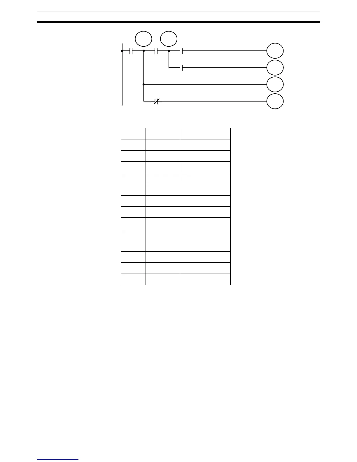
Address Instruction Data
0000 LD 0000
0001 OUT TR 0
0002 AND 0001
0003 OUT TR 1
0004 AND 0002
0005 OUT 0500
0006 LD TR 1
0007 AND 0003
0008 OUT 0501
0009 LD TR 0
0010 OUT 0502
0011 AND NOT 0005
0012 OUT 0503
When coding IL(02) and ILC(03), the mnemonic code will be the same re-
gardless of whether the instruction is drawn as branching instruction lines or
whether IL(02) is placed on its own instruction line. If drawn as branching
instruction lines, each branch line is coded as if it were connected to the bus
bar, i.e., the first condition on each branch line corresponds to a LD or LD
NOT instruction.
Interlocks
Converting to Mnemonic Code Section 7–2

Table of Contents

Other manuals for Omron SYSMAC C20P

Question and Answer IconNeed help?

Do you have a question about the Omron SYSMAC C20P and is the answer not in the manual?

Omron SYSMAC C20P Specifications

General IconGeneral
ManufacturerOmron
ModelSYSMAC C20P
Programming LanguageLadder Logic
I/O Points20
Input Voltage100-240V AC
Output TypeRelay
Number of Outputs8
Operating Temperature0-55°C

Summary

SYSMAC Programmable Controllers C20P/C28P/C40P/C60P OPERATION MANUAL

Notice:

OMRON Product References

Visual Aids

About this Manual:

Section 1 Precautions

Provides general precautions for using the Programmable Controller (PC).

Section 2 Background

Explains ladder-diagram programming basics and OMRON PC terminology.

Section 3 Hardware Considerations

Explains PC configuration and indicators.

Section 4 Memory Areas

Details memory division, allocation, and I/O management.

Section 5 Programming

Explains ladder-diagram programming elements and execution control.

Section 6 Instruction Set

Describes all programming instructions individually.

Section 7 Program Execution Timing

Explains program scanning and I/O coordination timing.

Section 8 Program Input, Debugging, and Execution

Covers program input, debugging, and system monitoring.

Section 9 Troubleshooting

Provides information on system error indications and downtime reduction.

Appendices

Offers tables of products, reference tables, and operational information.

PRECAUTIONS

1 Intended Audience

Manual for personnel with electrical systems knowledge, involved in FA systems.

2 General Precautions

User must operate according to specs; consult OMRON for critical systems.

3 Safety Precautions

Warning against disassembling units or touching terminals while power is supplied.

4 Operating Environment Precautions

Lists unsuitable operating environments such as extreme temperatures or humidity.

5 Application Precautions

Precautions for grounding, power supply, voltage limits, shielding, and handling.

SECTION 1 Background

1–1 Introduction

Introduces the PC and the manual's scope.

1–2 Relay Circuits: The Roots of PC Logic

Explains the origin of PC logic from relay-based control systems.

1–3 PC Terminology

Defines crucial terms for understanding PC operation.

1–4 OMRON Product Terminology

Explains OMRON product naming conventions like CPU and I/O Units.

1–5 Overview of PC Operation

Outlines the basic steps for programming and operating a P-type PC.

1–6 Peripheral Devices

Lists and describes devices used for programming, debugging, and interfacing.

1–7 Available Manuals

Lists other manuals required for PC programming and operation.

SECTION 2 Hardware Considerations

2–1 Introduction

Provides information on hardware aspects relevant to programming.

2–2 Indicators

Explains CPU indicators that provide visual operation information.

2–3 PC Configuration

Details the types of Units that can be used to build P-type PCs.

SECTION 3 Memory Areas

3–1 Introduction

Describes various memory areas used for data and program storage.

3–2 Data Area Structure

Explains how data areas are organized and accessed (bits and words).

3–3 IR Area

Details the IR area for I/O points and work bits.

3–4 SR Area

Contains flags and control bits for monitoring system operation.

3–5 DM Area

Used for internal data storage and manipulation, accessible by word.

3–6 HR Area

Used to store and manipulate data, retaining status during power interruptions.

3–7 TC Area

Used for programming timers and counters, holding flags and values.

3–8 TR Area

Provides bits for enabling branching in ladder diagrams.

SECTION 4 Programming

4–1 Introduction

Explains basic steps and concepts for programming.

4–2 Instruction Terminology

Defines terms related to instructions used in ladder-diagram programming.

4–3 The Ladder Diagram

Explains ladder diagram structure, conditions, and logic.

4–4 Controlling Bit Status

Details instructions used to control individual bit status.

4–5 The End Instruction

Explains the mandatory END instruction for program execution.

4–6 Programming Precautions

Provides guidelines and warnings for drawing clear and correct ladder diagrams.

4–7 Program Execution

Describes how the CPU scans and executes the program.

SECTION 5 Instruction Set

5–1 Introduction

Introduces the PC instruction sets and their categorization.

5–2 Notation

Explains how instructions are referred to by their mnemonics.

5–3 Instruction Format

Details the structure of instructions, including operands and definers.

5–4 Data Areas, Definer Values, and Flags

Explains data areas, definers, and flags used with instructions.

5–5 Ladder Diagram Instructions

Covers instructions that correspond to conditions on the ladder diagram.

5–6 Bit Control Instructions

Details instructions for controlling individual bit status.

5–7 Interlock and Interlock Clear – IL(02) and ILC(03)

Explains how to use interlocks to enable branching and control execution.

5–8 Jump and Jump End – JMP(04) and JME(05)

Describes instructions for skipping program sections based on conditions.

5–9 End – END(01)

Explains the END instruction, marking the end of program execution.

5–10 No Operation – NOP(00)

Describes the NOP instruction, which performs no operation.

5–11 Timer and Counter Instructions

Covers instructions for timers and counters, including SV and TC numbers.

5–12 Data Shifting

Describes instructions for creating and manipulating shift registers.

5–13 Data Movement

Explains instructions for moving data between memory addresses.

5–14 Data Compare – CMP(20)

Details instructions used for comparing data contents of two words.

5–15 Data Conversion

Covers instructions for converting data formats between binary and BCD.

5–16 BCD Calculations

Explains instructions for performing mathematical operations on BCD data.

SECTION 6 Program Execution Timing

6–1 Introduction

Explains the importance of timing in program writing and debugging.

6–2 Scan Time

Defines scan time and explains its impact on PC operations.

6–3 Calculating Scan Time

Shows how to calculate scan time based on PC configuration and operations.

6–4 Instruction Execution Times

Lists execution times for instructions under various conditions.

6–5 I/O Response Time

Explains the time taken for PC to output a signal after receiving an input.

SECTION 7 Program Input, Debugging and Execution

7–1 Introduction

Provides procedures for inputting and debugging programs via a Programming Console.

7–2 Converting to Mnemonic Code

Explains how to convert ladder diagrams to mnemonic code for PC input.

7–3 The Programming Console

Details the Programming Console, its keyboard, and operating modes.

7–4 Preparation for Operation

Covers essential preparation steps like password entry and memory clearing.

7–5 Inputting, Modifying, and Checking the Program

Explains how to input, modify, and check programs using the console.

7–6 Program Backup and Restore Operations

Describes procedures for backing up and restoring program data using cassette tapes.

7–7 Debugging

Explains how to execute and correct execution errors in a program.

7–8 Monitoring Operation and Modifying Data

Details how to monitor and modify data, including timer/counter values.

SECTION 8 Troubleshooting

8–1 Introduction

Introduces self-diagnostic functions for identifying and correcting system errors.

8–2 Reading and Clearing Errors and Messages

Explains how to display and clear system error messages.

8–3 Error Messages

Categorizes and lists error messages, probable causes, and corrections.

8–4 Error Flags

Lists flags in the SR area used for troubleshooting and error detection.

Appendix A Standard Models

CPUs

Lists standard CPU models with their specifications, model numbers, and standards.

Expansion I/O Units

Lists standard expansion I/O units with specifications and model numbers.

Special Units

Lists special units like analog timers, I/O link units, and cables.

DIN Products

Lists standard DIN track and related accessories.

Factory Intelligent Terminal (FIT)

Lists the components included in the Factory Intelligent Terminal.

Graphic Programming Console (GPC)

Lists GPC models, carrying cases, and memory cassettes.

Appendix B Programming Instructions

Basic Instructions

Details fundamental ladder diagram instructions like LD, AND, OR, and OUT.

Special Instructions

Covers End, Interlock, Jump, and related special instructions.

Shift Register

Describes the SFT(10) instruction for creating bit shift registers.

Latching Relay

Explains the KEEP(11) instruction for defining a bit as a latch.

Reversible Counter

Details the CNTR(12) instruction for up-down reversible counters.

Differentiate Up/Down

Explains DIFU(13) and DIFD(14) for single-scan bit activation.

High-speed Timer

Describes the TIMH(15) instruction for high-speed timing.

Word Shift

Explains the WSFT(16) instruction for shifting data by word.

Compare

Details the CMP(20) instruction for comparing data.

Appendix C Programming Console Operations

System Operations

Covers basic operations like password input, buzzer control, and data clearing.

Programming Operations

Details operations like address designation, program input, read, and search.

Monitoring and Data Changing Operations

Explains bit/word monitoring, data changes, and SV modification.

Cassette Tape Operations

Describes saving, restoring, and comparing program memory data using cassette tapes.

PROM Writer Operations

Covers PC to PROM writer and PROM writer to PC operations.

Appendix D Error and Arithmetic Flag Operation

Appendix E Binary–Hexadecimal–Decimal Table

Appendix F Word Assignment Recording Sheets

Appendix G Program Coding Sheet

Glossary

Related product manuals