20
Link Unit can be used) and an Analog Timer Unit cannot be used with. The
rest of the Units can be in any order desired.
The tables on the following pages show the possible configurations for a
P-type PC. Although the tables branch to show the various possibilities at
any one point, there can be no branching in the actual PC connections. You
can choose either branch at any point and go as far as required, i.e., you can
break off at any point to create a smaller PC System.When implementing a
system there is a physical restriction on the total cable length allowable. The
sum of the lengths of all cables in the system must be limited to less than 1.2
meters.
The tables also show which words will be input words and which words will
be output words. All of these are determined by the position of the Unit. With
the C4P and C16P Expansion I/O Units, the type of Unit (input or output) de-
termines whether the input or output word is used.
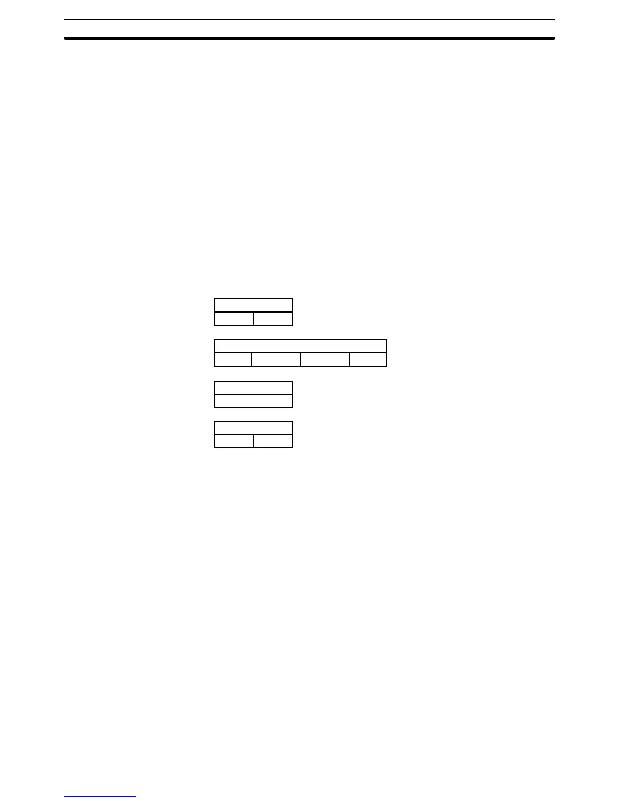
The symbols used in the table represent the following:
C20P/C28P
Input Output
C20P/C28P/TU/AN/LU
Input Output
C4K/C16P
Input or Output
C40P/C60P
Input Output
Input Output
C20P or C28P CPU Unit
C40P or C60P CPU or
Expansion I/O Unit
C4K or C16P Expansion I/O Unit
C20P Expansion I/O Unit, C28P Expansion I/O Unit,
Analog Timer Unit, Analog I/O Unit, or I/O Link Unit
IR Area Section 3–3