19
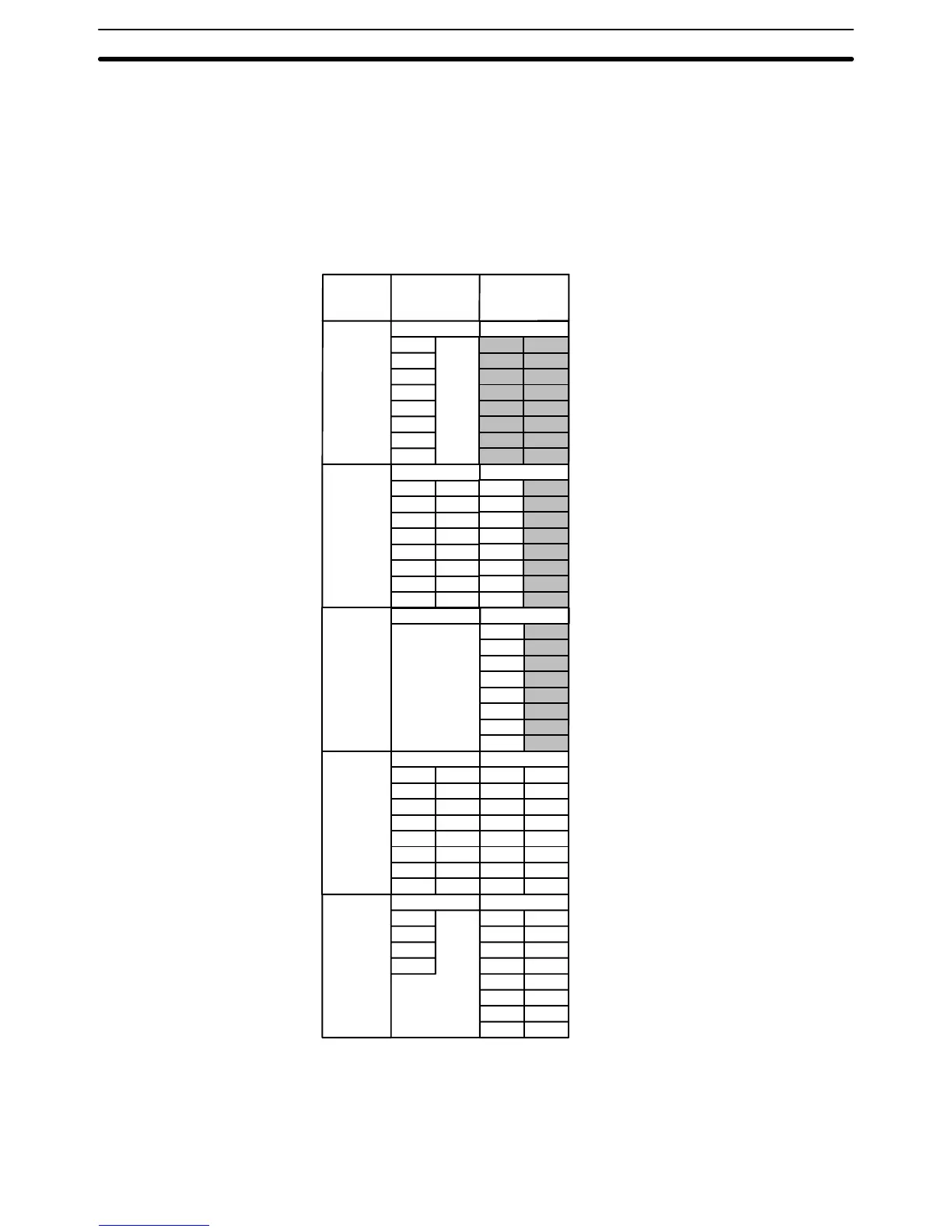
The following table shows which bits are allocated to each of the Special I/O
Units. Bits in the shaded areas can be used as work bits but not as output
bits. The word addresses depend on the Unit(s) that the Special I/O Unit is
coupled to. In all cases the first Special I/O Unit address for input and output
words is one more than the last address for input and output words used by
the Unit to which the Special I/O Unit is attached. For example, if the last
word address was IR 03, the first input or output word address for the Special
I/O Units will be IR 04. In the tables below “n” is the word allocated prior to
the Special I/O Unit.
IR (n + 1)
00
01
02
03
04
05
06
07
IR (n + 6)
00
01
02
03
04
05
06
07
08
09
10
11
12
13
14
15
IR (n + 1)
00
01
02
03
IR (n + 1)
00
01
02
03
04
05
06
07
08
09
10
11
12
13
14
15
IR (n + 6)
00
01
02
03
04
05
06
07
08
09
10
11
12
13
14
15
IR (n + 1)
Model Input bits Output bits
C1K–AD
C4K–AD
C1K–DA
C20–LK
011(–P)
C4K–TM
Cannot
be used
Cannot
be used
00
01
02
03
04
05
06
07
08
09
10
11
12
13
14
15
IR (n + 6)
00
01
02
03
04
05
06
07
08
09
10
11
12
13
14
15
IR (n + 6)
00
01
02
03
04
05
06
07
08
09
10
11
12
13
14
15
IR (n + 6)
00
01
02
03
04
05
06
07
08
09
10
11
12
13
14
15
Cannot
be
used
IR (n + 1)
A P-type PC consists of a CPU Unit plus one or more of the following Units:
Expansion I/O Units, Analog Timer Units, Analog I/O Units, or an I/O Link
Unit. All of these Units are connected in series with the CPU Unit at one end.
An I/O Link Unit, if included, must be on the other end (meaning only one I/O
I/O Bits Available in Special
I/O Units
PC Configuration and I/O
Word Allocation
IR Area Section 3–3