35
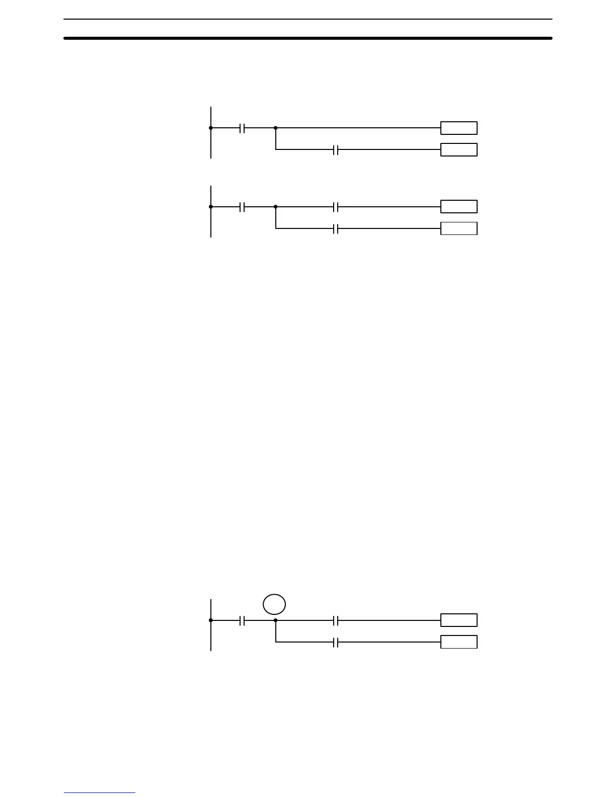
serving the previous condition. The following diagrams illustrate this. In both
diagrams, instruction 1 is executed before returning to the branching point
and moving on to the branch line leading to instruction 2.
Instruction 1
0002
0000
Instruction 2
Branching
point
Instruction 1
0002
0000
Instruction 2
Branching
point
Diagram B: Needs Correction
Diagram A: OK
0001
If, as shown in diagram A, the execution condition that existed at the branch-
ing point is not changed before returning to the branch line (instructions at
the far right do not change the execution condition), then the branch line will
be executed correctly and no special programming measure is required.
If, as shown in diagram B, a condition exists between the branching point
and the last instruction on the top instruction line, the execution condition at
the branching point and the execution condition at the end of the top line will
sometimes be different, making it impossible to ensure correct execution of
the branch line. The system remembers only the current execution condition
(i.e., the logical sum for an entire line) and does not remember partial logical
sums at points within a line.
There are two means of programming branching programs to preserve the
execution conditions. One is to use TR bits; the other, to use interlocks.
The TR area provides eight bits, TR 0 through TR 7, that can be used to tem-
porarily preserve execution conditions. If a TR bit is used as the operand of
the Output instruction placed at a branching point, the current execution con-
dition will be stored at the designated TR bit. Storing execution conditions is
a special application of the Output instruction. When returning to the branch-
ing point, the same TR bit is then used as the operand of the Load instruction
to restore the execution condition that existed when the branching point was
first reached in program execution.
The above diagram B can be written as shown below to ensure correct exe-
cution.
Instruction 1
0002
0000
Instruction 2
Diagram B: Corrected Using a TR bit
0001
TR 0
In terms of actual instructions the above diagram would be as follows: The
status of 0000 is loaded (a Load instruction) to establish the initial execution
condition. This execution condition is then output using an Output instruction
to TR 0 to store the execution condition at the branching point. The execution
condition is then ANDed with the status of 0001 and instruction 1 is executed
TR Bits
The Ladder Diagram Section 4–3