147
Exchanging Data with the CPU Unit Section 3-3
!WARNING Always verify the following points when setting CPU Unit I/O memory
addresses in the User Link Table:
• Words specified as “write” words in the User Link Table must not be allo-
cated to another function in the CPU Unit or other Units. If the specified
words are allocated to another function or Units, the PLC system may
operate in an unexpected manner and cause personal injury.
• When using a user link table to write bit data to I/O memory in the CPU
Unit. Never allow ladder programming or communications processes in
the CPU Unit to write to any bits in the words in which bits are written from
a user link table. Depending on the timing, any attempts to write to these
words from ladder programming or communications processes may be
ignored. Example: If tag A in a user link table writes to bit 00 of W000 and
an OUT instruction in the ladder program in the CPU Unit write to bit 01 of
W000, the write from the ladder program may be ignored.
Note Even if you delete a field terminal block from the block diagram, it will not be
deleted from the registered user link table. Also, if you delete the connection
line to the field terminal, the number of links that is given in the user link table
will change to 0, but even then the specified I/O memory in the CPU Unit will
be read and written for the specified conditions. To prevent reading and writing
the specified I/O memory in the CPU Unit, delete the link from the user link
table.
Creating the user link
table with the CX-Process
Tool
Use one of the following methods to create a user link table.
• Method 1: Registration on the User Link Table Edit Screen
• Method 2: Registration from the Block Diagram
1,2,3... 1. Method 1: Registration on the User Link Table Edit Screen
a. Select Edit User Link Table from the Settings Menu.
b. Right-click on the User Link Table Edit Screen and select Add from the
pop-up menu.
2. Method 2: Registration from the Block Diagram
a. Right-click on the block diagram and select Register/Link Input
(Read from CPU Memory) or Register/Link Output (Write to CPU
Memory) from the pop-up menu. A user link table block will be creat-
ed.
b. Select the block that was created, right-click, and select Register
Block Cell from the pop-up menu.
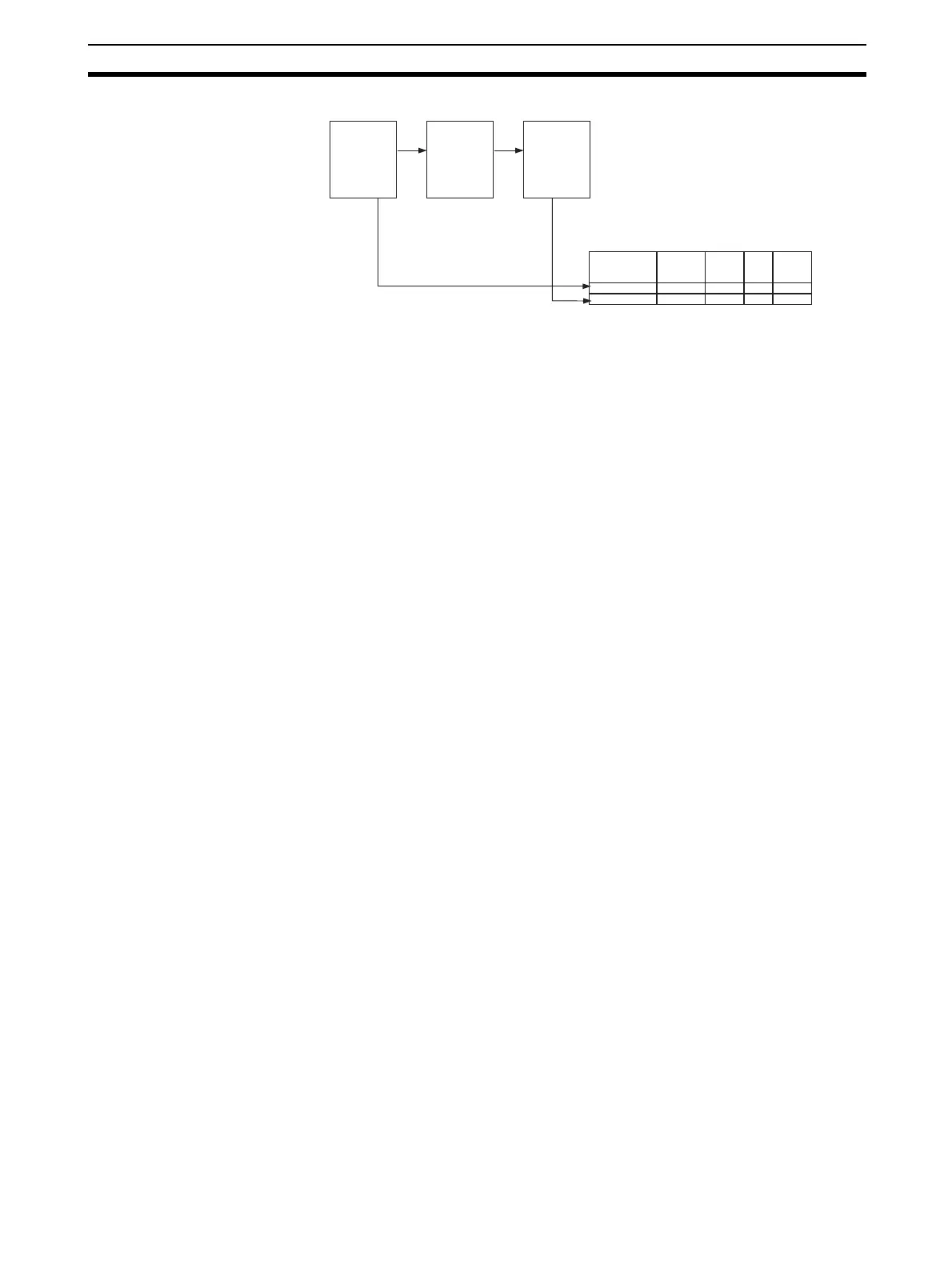
User Link Table
Tag name CPU Unit
address
Read/
Write
0%
range
100%
range
RA_CIO02000 CIO02000 Read 0 3000
WA_CIO02050 CIO02050 Write 0 4000
Field Terminal Function Block Field Terminal
1. Software connection of Field Terminals in Block Diagram
2. Automatic registration into table
2. Automatic registration into table