148
Exchanging Data with the CPU Unit Section 3-3
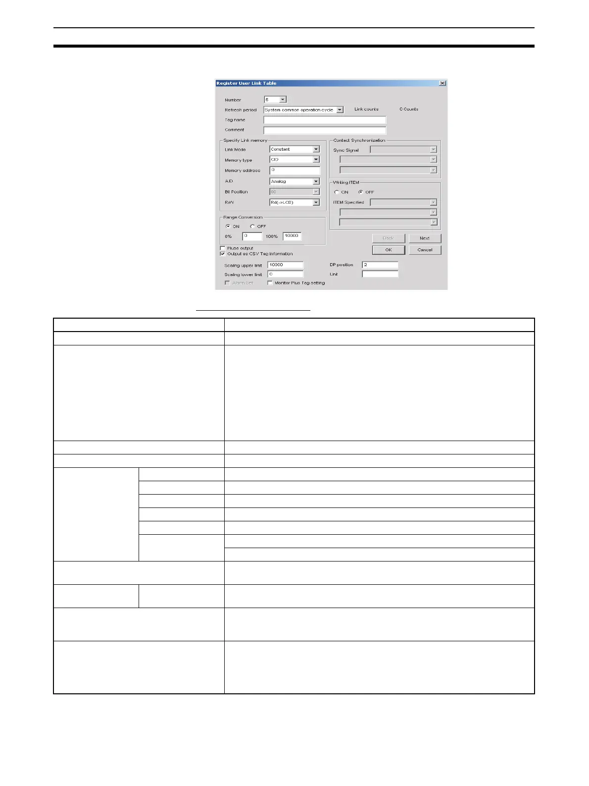
The following dialog box will be displayed for either method 1 or 2.
User Link Table Settings
Item Setting
Number Entry number
Refresh period The refresh cycle for CPU Unit data.
The cycle can be set to the system common operating cycle, 0.01 s, 0.02 s,
0.05 s, 0.10 s, 0.20 s, 0.50 s, 1.00 s, or 2.00 s
(If the user link table is pasted in a block diagram to make software connec-
tions and the function block data is downloaded to the Loop Control Board
with the Update User Link Table Refresh Cycle selection selected in the
CX-Process Tool, the setting made here will be ignored and data refreshing
with the CPU Unit will be performed on the operating cycle of the function
blocks that are the destination of the software connections.)
Tag Name 16 characters max., any text string
Comment 23 characters max., any text string
Specify Link mem-
ory
Link Mode Constant, On change, External sync
Memory Type Area in I/O memory of CPU Unit: CIO, W, H, DM, or EM0 (See note 2.)
Memory Address The address of the word in I/O memory to be allocated
A/D Analog or contact
Bit Position 00 to 15
R/W RD (To Loop Controller)
Wr (From Loop Controller)
Range Conversion ON/OFF
0% value and 100% value
Contact Synchroni-
zation
Synchronous Signal ITEM specified (function block address and ITEM number)
Read from ITEM/Write to ITEM ON/OFF
Specify a read ITEM and/or WRITE item (function block address and ITEM
number)
Pulse Output (See note 1.) Select to specify a one-shot pulse output when the signal changes from OFF
to ON. (Turns ON the output only once during the refresh cycle for user link
tables and writes to the I/O memory of the CPU Unit.)
Enabled only when A/D is a contact and R/W is Wr (from the Loop Control
Board).