29
Outline Section 1-1
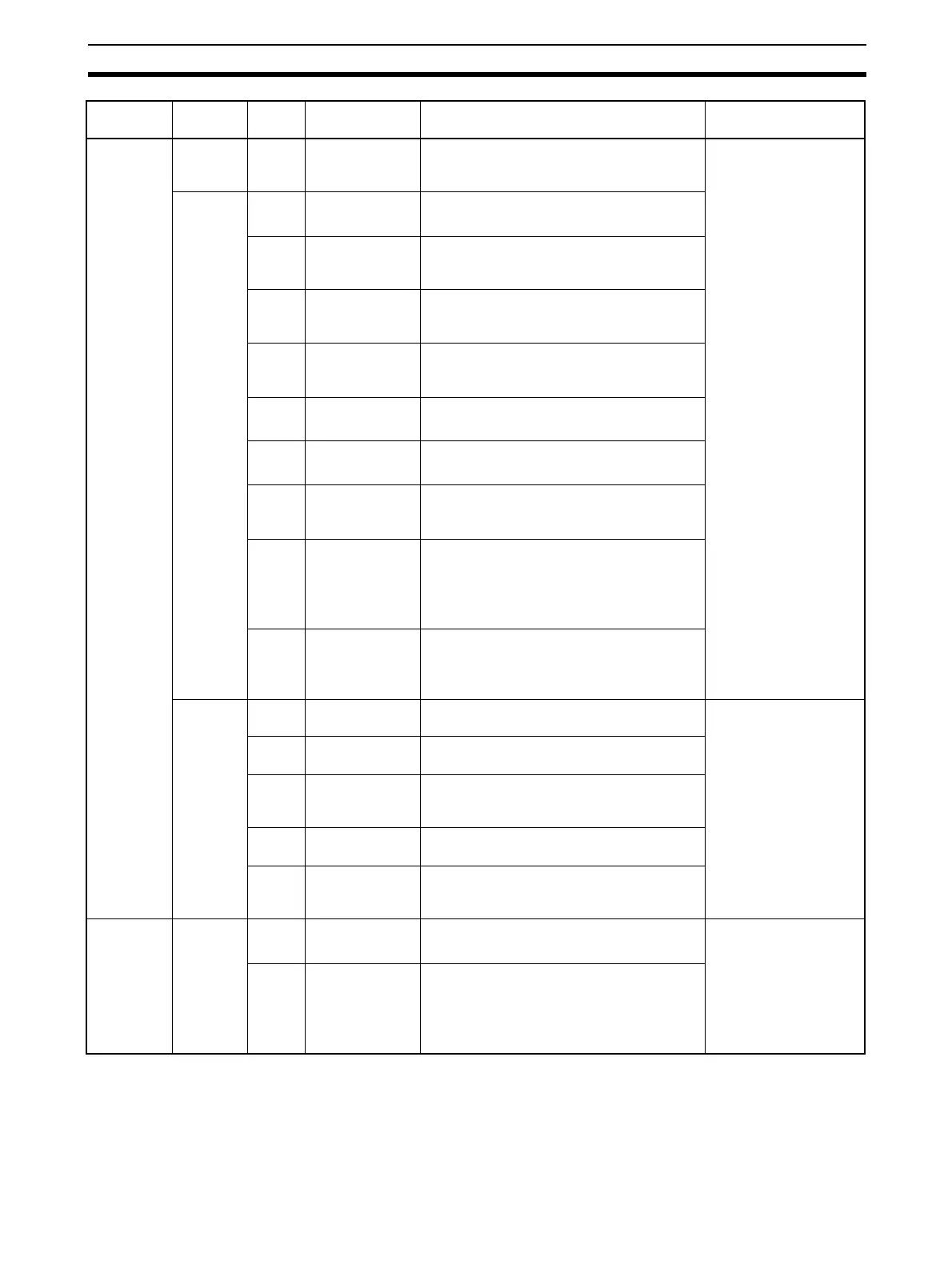
Operation
Block (con-
tinued)
Others 192
(See note
1.)
Analog/Pulse
Width Converter
Changes the ON/OFF duration ratio in a
constant cycle duration so that it is propor-
tional to the analog signal.
LCB05/05D: 001 to 500
LCB03: 001 to 300
LCB01: 001 to 050
Sequence
Operation
201
(See note
1.)
Contact Distrib-
utor
Connect contact signals between function
blocks in a 1: 1 connection.
202
(See note
1.)
Constant Com-
parator
Compares up to eight sets of analog sig-
nals and constants, and outputs the com-
parison results as contacts.
203
(See note
1.)
Variable Com-
parator
Compares up to eight pairs of analog sig-
nals, and outputs the comparison results as
contacts.
205
(See note
1.)
Timer 2-stage output type addition timer for fore-
cast values and reached values. Can also
output the present value.
206
(See note
1.)
ON/OFF Timer Timer for performing ON-OFF operation at
preset ON and OFF times.
207
(See note
1.)
Clock Pulse Manipulates and monitors ON/OFF valves
with open/close limit switches.
208
(See note
1.)
Counter 2-stage output type addition timer for fore-
cast values and arrival values. Can also
output the current value.
209
(See note
1.)
Internal Switch Temporary storage contact for accepting
relays in the Step Ladder Program block.
(Note: One internal switch is already allo-
cated as “temporary storage” in CX-Pro-
cess Tool.)
210
(See note
1.)
Level Check Checks an analog input for 8 levels and
outputs a contact corresponding to the
level. The level number is also output as an
analog value.
Contact
Type Con-
trol Target
221 ON/OFF Valve
Manipulator
Manipulates and monitors ON/OFF valves
with open/close limit switches.
LCB05/05D: 001 to 500
LCB03: 001 to 300
LCB01: 001 to 050
222 Motor Manipula-
tor
Manipulates and monitors motor operation.
223 Reversible
Motor Manipula-
tor
Manipulates and monitors reversible motor
operation.
224 Motor Opening
Manipulator
Inputs a target opening, and manipulates
an electric positional-proportional motor.
225 Switch Meter Manipulates and monitors multiple devices
(up to 8) such as ON/OFF valves, motors,
and pumps.
Sequential
Control
301
(See note
1.)
Step Ladder
Program
Performs logic sequence and step progres-
sion control.
LCB01: 701 to 720
LCB03/05/05D: 701 to
900
302
(See note
3.)
Sequence table Conditions and actions are listed in table
format to perform logic sequence or step
progression control.
Note: CS1W-LCB05/05D only; not sup-
ported by the CS1W-LCB01.
Category Type Block
Model
Block Name Function Allocatable Block
Address