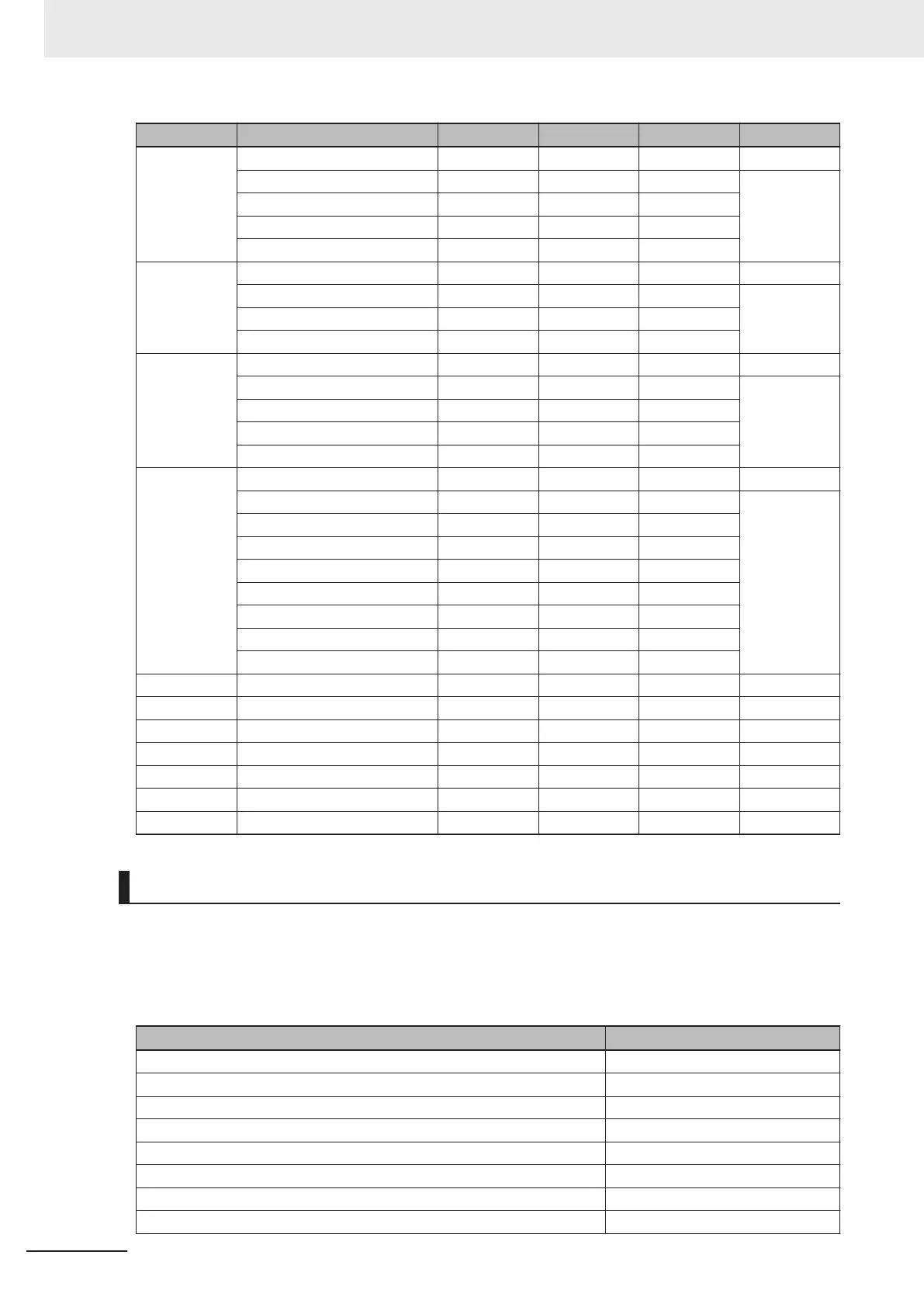
Member Name Data Type Bit Number Data Length Byte Offset
32 bit Output Control Echo DINT 4 Byte 8
Out1 Echo 0 1 bit
Out2 Echo 1 1 bit
Out3 Echo 2 1 bit
Reserved 3 - 31 29 bit
32 bit External Input Status DINT 4 Byte 12
Trigger 0 1 bit
New Master 1 1 bit
Reserved 2 - 31 30 bit
32 bit External Output Status DINT 4 Byte 16
Out1 0 1 bit
Out2 1 1 bit
Out3 2 1 bit
Reserved 3 - 31 29 bit
32 bit Device Status DINT 4 Byte 20
Reserved 0 1 bit
New Master Requedted 1 1 bit
Reserved 2 - 7 6 bit
Scanning Disabled 8 1 bit
Reserved 9 - 15 7 bit
In Read Cycle 16 1 bit
Actively Scanning 17 1 bit
Reserved 18 - 31 14 bit
32 bit
Read Cycle Sequence Counter
UDINT 0 - 31 4 byte 24
32 bit Trigger Count UDINT 0 - 31 4 byte 28
32 bit Decode/Matchcode Count UDINT 0 - 31 4 byte 32
32 bit Mismatch Count UDINT 0 - 31 4 byte 36
32 bit No Read Count UDINT 0 - 31 4 byte 40
32 bit Decode Data Length UDINT 0 - 31 4 byte 44
Decode Data String SINT[128] 0 - 1024 128 byte 48
MXL/SLC Input Assembly (Instance ID: 102)
Compared to the Large Input Assembly, the MXL/SLC Input Assembly holds the more detailed Device
Status information and Read result character strings of up to 184 bytes. When reading multiple sym-
bols, the Read strings are output delimited by Separator Characters.
MXL/SLC Input Assembly Member Structure
Member Name Size (Bytes)
INFO BITS 1
RESERVED 1
CONFIGURATION CHANGE DETECTION 1
RESERVED 1
DEVICE STATUS 4
FAULT CODE 4
COUNTERS 24
READ CYCLE REPORT 8
Appendices
A - 8
V430-F Series Autofocus Multicode Reader User Manual for Communication Settings

 Loading...

