・AutoImage Photometry Enabled
This bit is set to 1 when Auto Photometry is used.
This bit is set to 0 when AutoImage Photometry is complete.
・AutoImage Photometry Complete
This bit is set to 1 when AutoImage Photometry processing is complete. If an error occurs, it is out-
put by Fault Code area.
・Output 1 Status
Indicates the current state of the Parallel OUTPUT 1 signal.
・Output 2 Status
Indicates the current state of the Parallel OUTPUT 2 signal.
・Output 3 Status
Indicates the current state of the Parallel OUTPUT 3 signal.
・Buffer Overflow
This bit is set to 1
when the read string length exceeds the size of the Decode Data area.
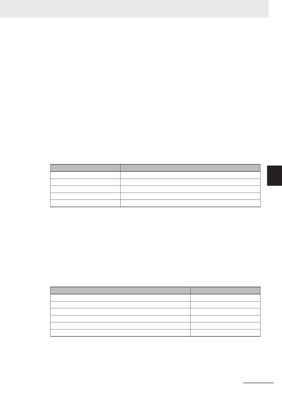
• Fault Code
Outputs Error information when a code reader error occurs.
It can be set from the Command field of the Output Assembly.
Bit State
0 Command Error Detected
1 Communication Error
2 Reserved
3 Host Port Buffer Overflow
4 - 31 Reserved
・Command Error Detected
This bit is set to 1 when a Serial command fails to be executed.
・Communication Error
This bit is set to 1 when a data error condition is detected in Serial (RS-232C) communication.
・Host Port Buffer Overflow
This bit is set to 1
when a character string larger than the size set for the Decode Data area is re-
ceived.
• Counters
Various counters of Read results after starting the device are output.
These counters can be set from the Command Field/Area of the Output Assembly.
Counters Size (Bytes)
No Read Read Cycle Counter 4
Mismatch per Read Cycle Counter 4
No Read Counter 4
Trigger Counter 4
Matchcode Counter 4
Mismatch Counter 4
・No Read Read Cycle Counter
Outputs the total number of Read Cycle No Reads.
・Mismatch per Read Cycle Counter
Outputs the total number of Read Cycle Mismatches.
・No Read Counter
Appendices
A - 11
V430-F Series Autofocus Multicode Reader User Manual for Communication Settings
A-2 EtherNet/IP Detailed Specifications
A
A-2-1 Assembly Memory Allocation

 Loading...

