Bit
15 14 13 12 11 10 9 8 7 6 5 4 3 2 1 0
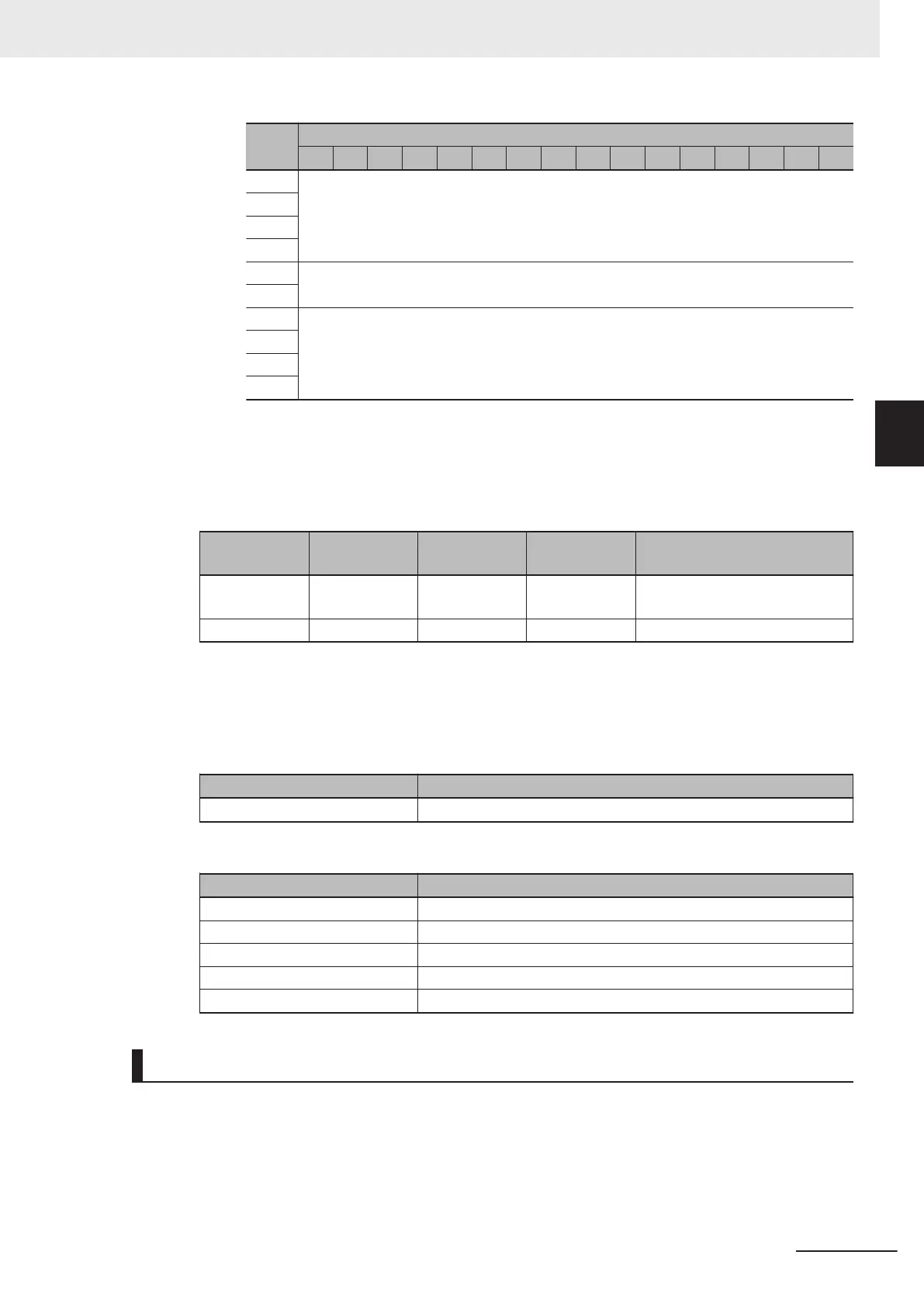
+12 Read Cycle Information (READ CYCLE REPORT)
+13
+14
+15
+16 Number of characters in Read data (DECODE LENGTH)
+17
+18 The content of the Read data (DECODE DATA)
…
...
+89
2 Defining the Variables
Define variables for the data links for the communications area data that is used in EtherNet/IP
communications.
These variables use the data types that were defined above in procedure 1.
Variable Variable type
Network Pub-
lish attribute
Data type Application
EIPOutput Global variable Output S_EIPOut-
put197
For data links to the Output Area
EIPInput Global variable Input S_EIPInput102 For data links to the Input Area
3 Accessing the Communications Areas from the User Program
The defined variables are used to access the communications areas for the Sensor using the
following
Output Area
Signal name Variable name
Trigger EIPOutput.COMMANDS.Trigger
Input Area
Signal Name Variable name
Online EIPInput.DEVICE_STATUS.Online
Trigger_Acknowledged EIPInput.DEVICE_STATUS.Trigger_Acknowledged
Decoding EIPInput.DEVICE_STATUS.Decoding
DataIsReady EIPInput.DEVICE_STATUS.DataIsReady
Decode_Data EIPInput.DECODE_DATA
Command Control Example
Here is an example of how Command Control is executed in EtherNet/IP communications between a
PLC and the code reader.
Read a Code and Store the Read String Output on the PLC
<Example T
ag Sets and Connection Settings>
• Input Assembly: MXL/SXL Input Assembly (102)
3 Controlling Operation and Data Output with Ethernet
3 - 17
V430-F Series Autofocus Multicode Reader User Manual for Communication Settings
3-1 Controlling Operation and Data Output with Ether-
Net/IP
3
3-1-9 Accessing the NJ-series Controller Communication Areas using Variables

 Loading...

