A
Troubleshooting
A-73
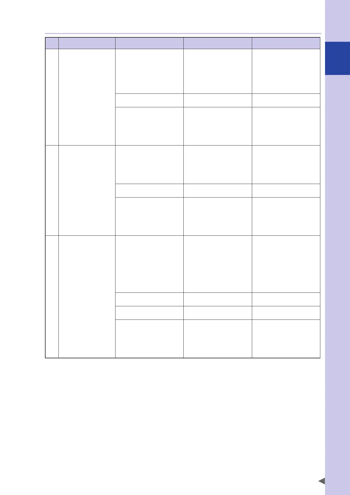
2.3.3 I/O
Symptom Possible cause Check items Corrective action
1 The command does not
work even when the
dedicated input signal is
supplied.
• No 24 V DC is supplied. • Check the I/O interface
connector stop signal and
24V-power supply
connections.
• Check DI06 (stop) on the
"MONITOR" screen displayed
on the programming box.
• Supply 24 V DC.
• A problem in signal
connection occurred.
• Check the I/O interface
connector wiring.
• Correct the I/O interface
connector wiring.
•
An alarm occurred.
• Connect the programming box
and check the alarm by using
self-diagnosis.
• Check the 7-segment LED
display on the front of the
controller.
• Check the cause from the
alarm information.
• Take the corrective action.
2 The dedicated output
signal is not output.
• No 24 V DC is supplied. • Check the I/O interface
connector 24V-power supply
connections.
• Check DI04 on the
"MONITOR" screen displayed
on the programming box.
• Supply 24 V DC.
• A problem in signal
connection occurred.
• Check the I/O interface
connector wiring.
• Correct the I/O interface
connector wiring.
•
An alarm occurred.
• Connect the programming box
and check the alarm by using
self-diagnosis.
• Check the 7-segment LED
display on the front of the
controller.
• Check the cause from the
alarm information.
• Take the corrective action.
3 The general-purpose I/O
signal is not output.
• No 24 V DC is supplied. • Check the I/O interface
connector 24V-power supply
connections.
• Check DI04 on the
"MONITOR" screen displayed
on the programming box.
• Check the I/O interface
24V-power supply
connection.
• Supply 24 V DC.
• A problem in signal
connection occurred.
• Check the I/O interface
connector wiring.
• Correct the I/O interface
connector wiring.
• A problem in I/O interface
setting occurred.
• Check the ID setting of the
I/O interface.
• Correct the ID setting of the
I/O interface.
•
An alarm occurred.
• Connect the programming box
and check the alarm by using
self-diagnosis.
• Check the 7-segment LED
display on the front of the
controller.
• Check the cause from the
alarm information.
• Take the corrective action.