3
Installation
3-12
9. Connecting the brake power supply
When there are two or more brake axes, an external brake power supply is needed. Prepare a 24 V 10 W
power supply for each axis.
NOTE
The brake power shares with the power source supplied to the parallel I/O board.
For details, refer to "1.2 Power supply" and "1.3 Power connector wiring work" in Chapter 4.
10. Precautions for cable routing and installation
10.1 Wiring methods
When performing the cable wiring to the controller, strictly observe the following cautions to prevent
malfunction due to noise.
CAUTION
As a general guide keep the specified cables separated at least 100 mm from each other.
1. Keep the external device cable, robot cables, power cable and other equipment power lines away from each
other. Never bundle them together.
2. The wiring of electromagnetic contactors, induction motors, solenoid valves or brake solenoids should be
separate from the external device cable and robot cable. Never pass them through the same conduit or
bundle them together.
3. The ground wire should be short.
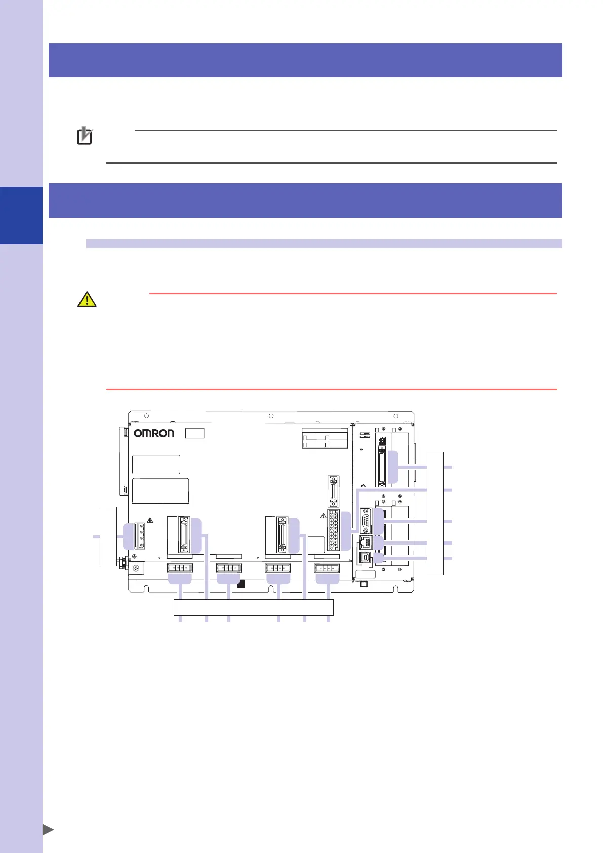
For each cable name, see the figure below.
BAT3
BAT4
BAT2
YRCX
Robot connection
Power
External device connection*
M4
EN
USB
COM
ROB I/O
3-4
SAFETY
1 3
2
4
PB
OPTION
1
2
3
4
PWR
AC IN
L
N
L1
N1
M1 M2 M3
ROB I/O
1-2
* External devices: DIO, SAFFTY, COM, Ethernet, and USB, etc.