2
System overview
2-3
2. Name of each part and control system
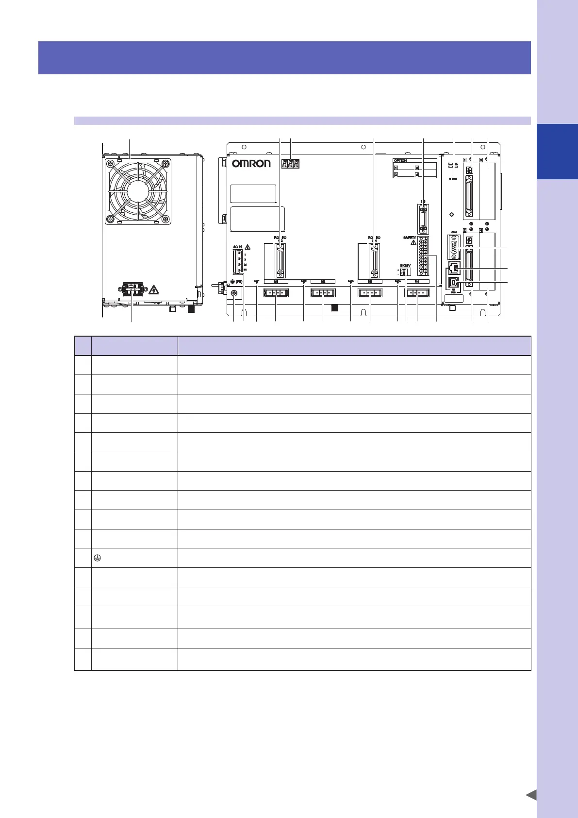
The YRCX external view and the control system basic diagram are shown below.
2.1 YRCX external view
YRCX
16
14
19 9 9 9 151 1 1 3 8 8
13 8 842 2
5
6
7
11
10
12
Panel display (name) Function
1
M1/M2/M3/M4 These connectors are used to drive the servo motor.
2
ROB I/O [1-2/3-4] These connectors are used for the servo motor position signal, origin sensor signal and brake control.
3
SAFETY This safety I/O connector is used for emergency stop and so on.
4
PB This connector is used for the programming box.
5
COM This connector is used for the RS-232C.
6
EN This connector is used for the Ethernet.
7
USB This connector is used for the USB.
8
(OP.) 1/2/3/4 These are option ports. Up to four option boards can be installed on them.
9
BAT [1/2/3/4] These connectors are used for the absolute backup batteries.
10
AC IN [L/N/L1/N1] These I/O connectors are used for the control power or main power supply (motor drive power supply).
11
(PE) This is the ground terminal. Class D grounding is required.
12
"PWR" LED This lights up when the power is turned ON.
13
7SEG LED This indicates the controller or robot status.
14
FAN
This fan ensures that the temperature inside the controller is kept at a fixed level.
When installing the controller, keep a clearance of 50 mm or more not to close the fan opening.
15
BK24V This is an external 24 V input power connector for the brake when using two or more axes as brakes.
16 RGEN
This is a regenerative unit connector for the expansion.
For the standard specifications, connect the thermal sensor shorting connector.