2
System overview
2-2
1.2 Axis configuration for the YRCX
The axis configuration for the OMRON YRCX robot controller is shown below.
Controller Robot
[1]
Robot
[4]
Normal axis
Normal axis
Auxiliary axis
Auxiliary axis
Robot [1 to 4]
An aggregate of axes making up one robot. Up to four robots can be controlled.
Normal axes
Indicate the axes composing the main robot. These can be moved with the robot language MOVE command.
Auxiliary axes
Indicate the single axes composing the main group. These cannot be moved with the robot language MOVE
command. Use the DRIVE command to move these axes.
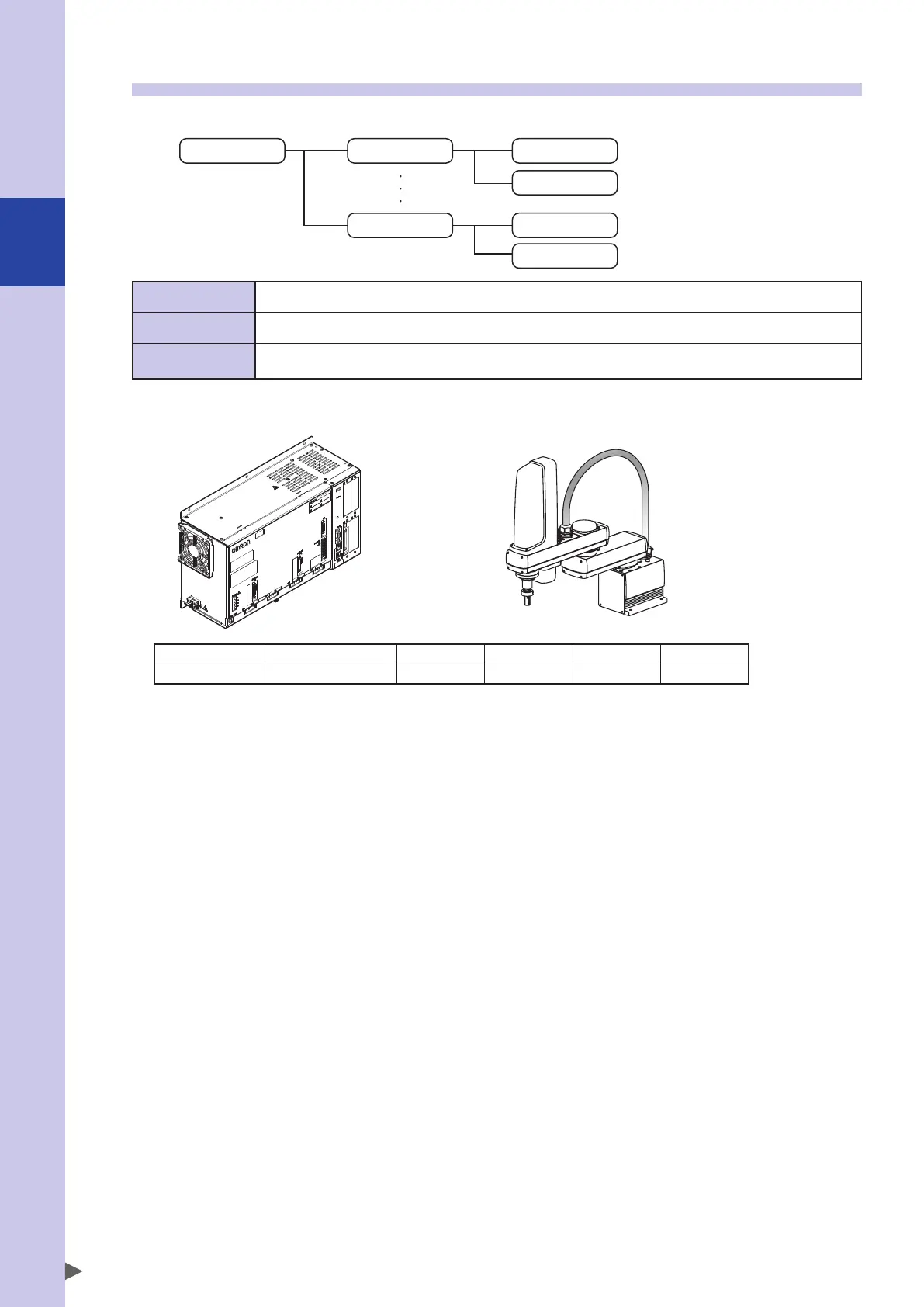
Example 1: 4-axis SCARA robot, 1 unit
YRCX
Robot number Robot type M1 M2 M3 M4
1 SCARA robot X Y Z R