74
GB
3 Device and Functional Description
1505093, Edition 2012-05, Version 5
3.2 Validity of these Operating Instructions
Only valid when combined with the
Installation and Operating Instructions
of the Vario View flat screen supports
The pendant system and the Vario View flat screen support a, b are described in sep-
arate Installation and Operating Instructions.
These Operating Instructions of the pendant system are only valid and complete when
combined with the Installation and Operating Instructions of the Vario View flat screen
support a, bs.
For information on installation and operation of the Vario View flat screen support a, b
refer to the following documents:
• Installation Instructions: No. 1522529
• Operating Instructions: No. 1522530
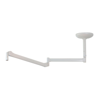
3.3 Appliance description
Canopy / wall bearing The points for connecting the electrical cables of the pendant system are located under-
neath the canopy / wall bearing 1. The canopy / wall bearing 1 may only be removed
by specialist personnel authorised by the operator.
Ceiling tube
(ceiling-mounted version only)
The ceiling tube 2 (ceiling-mounted version only) compensates different ceiling heights
in order to ensure that the adaption 7 - 9 with the end device (e.g. flat screen, OR lamp,
etc.) is positioned at the working height desired.
Extension arm The extension arms 3 with the internal supply cables (e.g. for a flat screen) can be
swiveled 330 degrees, and with internal plug couplings e.g. for OR lamps >360 degrees.
Twist protection In order to prevent the internal supply cables tearing off, the swivel range of the extension
arm 3 is restricted.
Spring arm with
internal supply cables
The spring arm 4 with the internal supply cables, e.g. for a flat screen, can be swiveled
330 degrees horizontally.
Twist protection In order to prevent the internal supply cables tearing off, the swivel range of the spring arm
4 is restricted.
Spring arm with
internal plug couplings
The spring arms 4 - 6 with internal plug couplings, e.g. for OR lamps, can be rotated
>360 degrees.
In addition, the spring arms 4 - 6 are height adjustable.
Vertical lift
of the spring arms
In order to prevent the spring arm 4 - 6 hitting the ceiling, its vertical lift can be restrict-
ed accordingly. The vertical lift was defined during installation.
Adaptations The adaptions 7 - 9 serve as a support for holding the end devices (e.g. flat screen, OR
lamp, etc.) as specified in
“Chapter 12, Optional Accessories, on page 107”
.