86
GB
8 Dismantling / Mounting in Case of Service
1505093, Edition 2012-05, Version 5
8.4 Mounting the end device to the ACROBAT2000 spring arm
Follow the safety instructions
Follow the general safety instructions prescribed in
“Chapter 8.1” on page 80
.
Maximum loading capacity
Calculate the maximum loading capacity as described in
“Chapter 8.2.3” on page 82
.
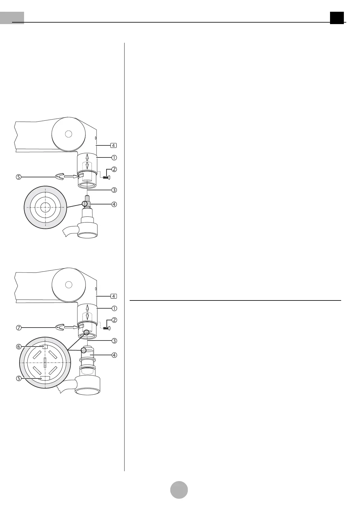
Figure 10: Version with 3-pole plug cou-
pling
Preparing the installation
(See "Figure 10")
1. Unscrew the sleeve securing screw M3 x 8mm 2 and push the sleeve 1 upwards.
2. Screw the sleeve securing screw M3 x 8mm 2 back in in order to fasten the
sleeve 1.
3. Remove the securing segment 5 using a suitable slotted screwdriver.
Only for version with 3-pole plug coupling
(See "Figure 10")
1. Grease the pivot groove and the pivot 4 using a suitable friction bearing grease
(e.g. Microgleit GP 360).
2. Position the pivot with 3-pole plug coupling 4, keeping it straightly aligned, and
establish the assembly connection 3 by gently pushing towards the spring arm 4.
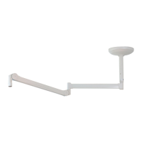
Figure 11: Version with 5-pole plug cou-
pling
Only for version with 5-pole plug coupling
(See "Figure 11")
1. Grease the pivot groove and the pivot 4 using a suitable friction bearing grease
(e.g. Microgleit GP 360).
NOTE – Plug positioning through the grooves
•The 5-pole plug coupling 4 has a narrow groove 6 and a wide groove 5.
• To establish the plug connection 3, the grooves 5/6 must fit into the corresponding
grooves of the counter piece.
2. Position the pivot with 5-pole plug coupling 4, keeping it straightly aligned, and es-
tablish the assembly connection 3 by gently pushing towards the spring arm 4.