98
GB
9 Adjustments
1505093, Edition 2012-05, Version 5
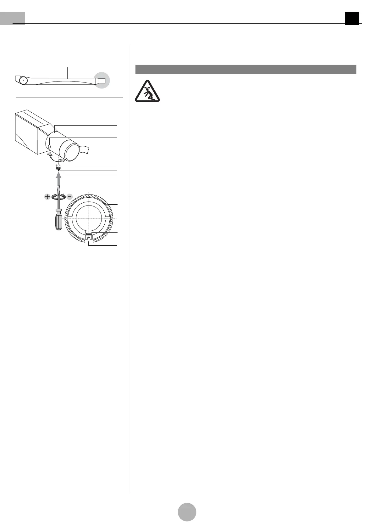
Figure 25: Adjusting the brake force on the
ACROBAT 2000 NRH spring arm
9.3.2 Adjusting the brake force on the ACROBAT2000 NRH spring arm
(See "Figure 25")
Pendant system crashing
The brake screw 3 is designed as a slotted screw:
• No other screws must be loosened.
Tool to be used
Use a suitable slotted screwdriver.
1. Turn the fitting aperture 2 in the cover 1 downwards.
•The brake screw 3 is located at the bottom of the connection.
To increase the brake force
• Insert the slotted screwdriver into the brake screw 3 and alternately turn with the
same number of revolutions in the clockwise (+) direction as illustrated in the
Figure 4.
To reduce the brake force
• Insert the slotted screwdriver into the brake screw 3 and alternately turn with the
same number of revolutions in the anti-clockwise direction (–) as illustrated in the
Figure 4.
2. Perform a function test.
1WARNING