101
GB
1505093, Edition 2012-05, Version 5
9 Adjustments
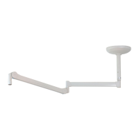
Figure 29: Adjusting the vertical lift on the
ACROBAT LCH spring arm
9.4.3 Adjusting the vertical lift on the ACROBAT LCH spring arm
(See "Figure 29")
Tool to be used
Use the pin (Ø 4mm x 110mm) available as an accessory included in the scope of
delivery.
Dismantling the cover panels
1. Unscrew 2 countersunk Phillips screws M3 x 6 mm 2.
2. Gently disengage each cover panel 5 on the 2 staggered straps 4 using a suitable
slotted screwdriver.
3. Remove the 2 cover panels 5.
Adjusting the vertical lift
4. Insert the pin (Ø4 mm x 110 mm) into the perforated adjusting nut in the adjusting
aperture 1.
To reduce the swivel range
• Turn the adjusting nut 1 upwards in the anti-clockwise (–) direction as illustrated in
the Figure.
To extend the swivel range
• Turn the adjusting nut 1 downwards in the clockwise (+) direction as illustrated in the
Figure.
Mounting the cover panels
5. Mount the cover panels 5 as described in
“Chapter 9.3.3” on page 99
.
6. Perform a function test.