64
4.4 INSTALLING THE EQUIPMENT
To perform the balancing measurements, you should have a triggering device and at least one vibration sensor
available. Take care to not change the position of the sensors during the entire balancing process.
4.4.1 Vibration sensor
Note: as phase measurement is required, Balancing module cannot be used with the WLS Sensor. This module
does not take in account the setting: Accelerometer link: Wire or Wireless (see § 2.2).
It is possible to use the following type of sensor:
Accelerometer
Velocimeter
Proximity probe
It is advisable to locate the measurement points on the bearings. Indeed, vibrations created by the rotor are
transmitted to the frame at this point. The sensor (accelerometer, a velocimeter) must be fixed onto the machine
(with a cementing screw, stud or a magnet) in order to obtain a proper connection and a well-determined position
for the sensor.
Several measurement points may be needed. The required number of points is related to the type of machine to be
balanced.
Connection:
1-plane balancing: vibration sensor is connected on channel 1 (Connector A)
2-plane balancing:
o point 1 is connected on channel 1 (Connector A)
o point 2 is connected on channel 2 (Connector B)
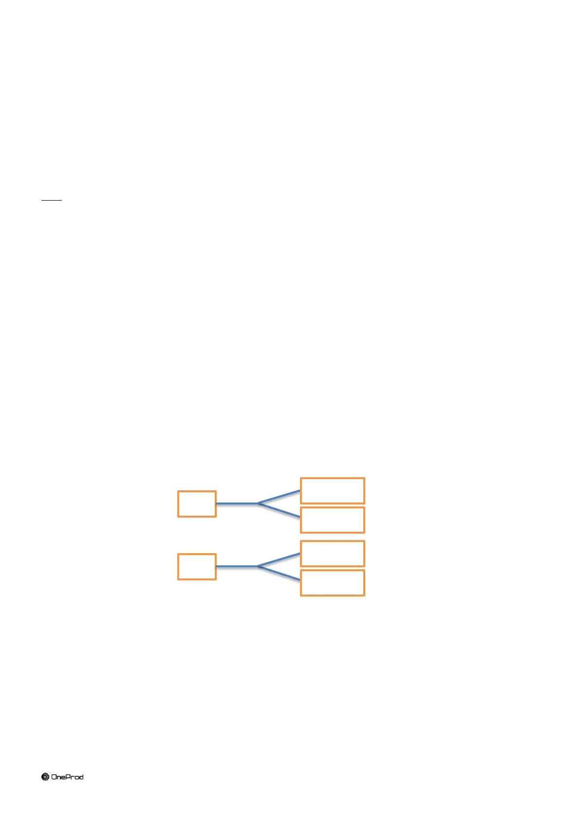
For 3 or 4-plane balancing, 1 or 2 Y adaptors are needed:
Y adaptor with ECTA output connector: ref FLC1003000 ECT-2ECT-ADPT_Y
Y adaptor with BNC output connector: ref FLC1004000 ECT-2BNC-ADPT_Y
3-plane balancing: 1 Y adaptor is needed on connector A
o point 1 is connected on channel 1
o point 2 is connected on channel 2
o point 3 is connected on channel 3
4- plane balancing: 2 Y adaptors are needed
o point 1 is connected on channel 1
o point 2 is connected on channel 2
o point 3 is connected on channel 3
o point 4 is connected on channel 4