39
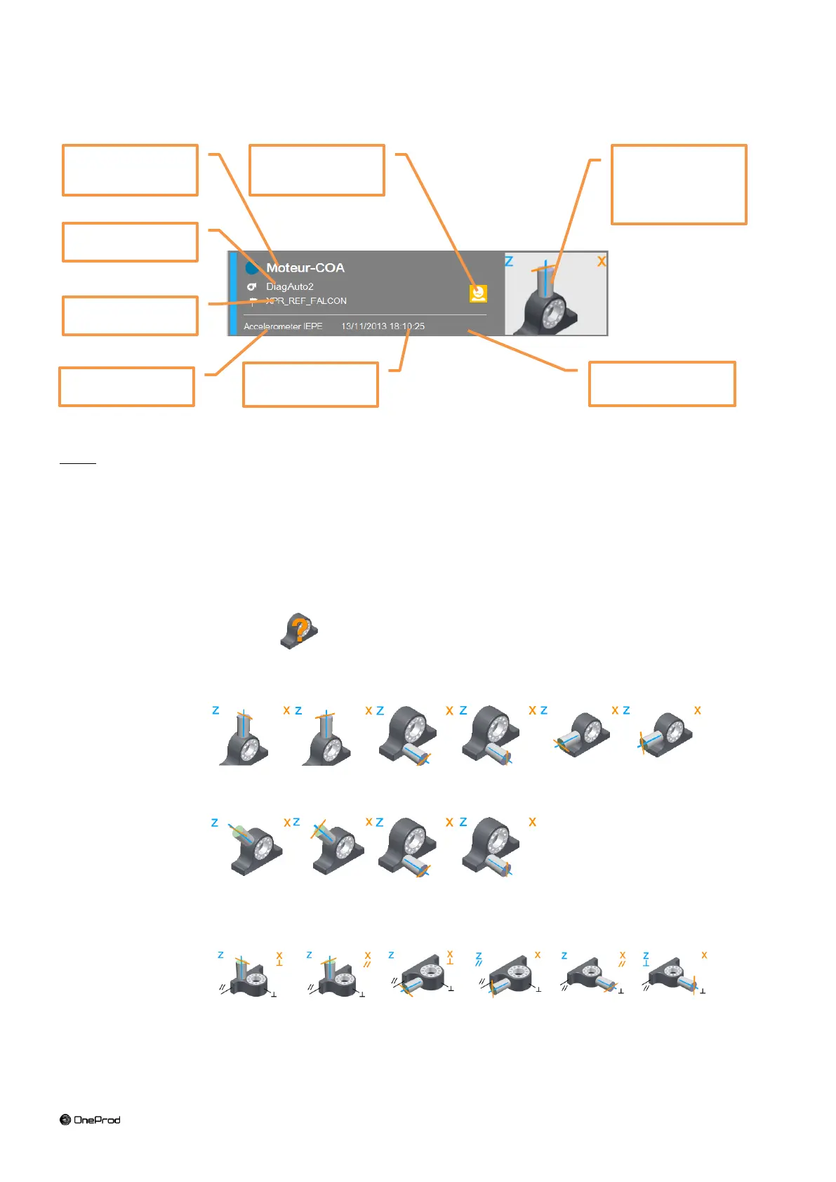
3.5.1 Header description
Notes:
* Only for machine created with NEST machine setup in “Automatic diagnosis” mode and on instrument equipped
with the “Diagnosis” option.
** Sensor pictogram or picture:
Position pictogram:
o For tri-axial measurement it is first necessary to select the pictogram indicating the position of
sensor on the bearing. It is only necessary to do it during the first measurement as the selection is
saved on the PC database when the route is downloaded.
To set it click on and select the sensor pictogram corresponding to the position of the
sensor on the bearing. For WLS sensor, the X axis is marked by ACOEM or ONEPROD logo and a
point at the base of the sensor.
For horizontal shaft and Axial (A), Horizontal (H) and Vertical (V) directions
For horizontal shaft and Axial (A), Radial oblique 1 (1) and Radial oblique 2 (2) directions
For vertical shaft and Axial (A), Radial main (//) and Radial perpendicular (P or )
directions
*** In NEST machine setup it is possible to indicate for each machine the definition of the
main direction (e.g., North-South…)
Measurement
point or location
Main direction for
vertical machine ***
Sensor
pictogram** or
picture ****