12
5
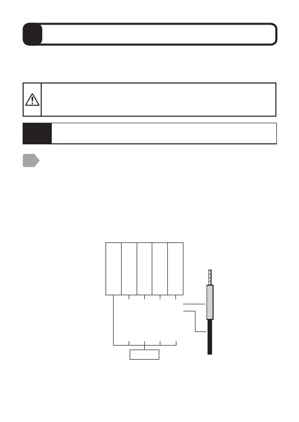
Wiring
Before wiring, turn off the power switch of SC-U1 or
disconnect the power cable from the supply source and wire
the power cable after all the other wiring is complete.
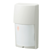
Connect the sensor to SC-U1.
・
The cable clamp fits the cable sheath diameter of 6 to 8 mm.
・
The sensor cable must be shielded (CVV-S) with a nominal
cross-sectional area of 0.2 to 1.25 mm
2
.
・
Refer to “Extension of sensor cable” P.11 for extension of the
sensor cable.
To extend the sensor cable, connection using pull box is recommended.
・
Wire the terminal block according to the color of the tip of each wire.
When wiring is cut and used, refer to the color shown in parentheses
() to correctly wire the terminal block.
Use this product by connecting to Universal Transmitter SC-U1.
For installation and wiring to SC-U1, refer to the "Universal Transmitter
SC-U1 Installation Manual".
1
Caution
Make sure that the breaker of SC-U1 is not turned off.
Sensor
power
supply
Signal
input
(RS485)
Blue
(Black)
Red
(Red)
Black
(Green)
White
(Blue)
Shielded wire
Power supply +
Power supply -
RS485 A
RS485 B