Relay Setting
18
Maintenance output setting
Set a maintenance timer for any cycle (“Maintenance timer” P.42) to notify
the user when the set period has elapsed.
Use this for notification of sensor maintenance, replacement of
consumables, and overhaul timing.
Check notifications by the relay output and dedicated cloud server (SC-U1
and GW connected).
For more information about checking notifications on the cloud server, refer
to the cloud server’s help.
Set notification of sensor cap replacement timing.
Sensor cap output setting
For operation, refer to the "Universal Transmitter SC-U1 Operation
Manual", "5.4 Relay Setting" and "
◆
Maintenance output setting".
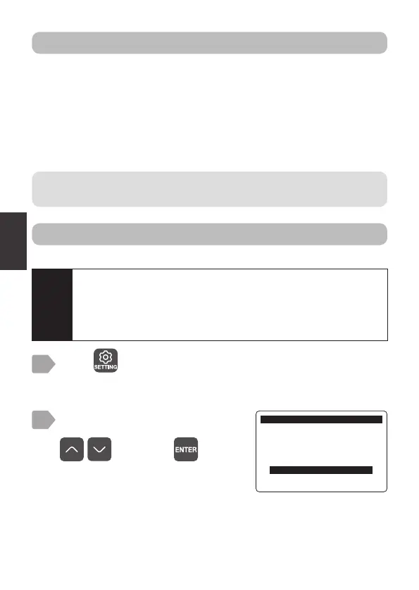
Press .
The sensor selection display is displayed.
1
Select [Relay Setting] using
, and press .
2
6HWWLQJ
6HWWLQJ0HQX
6HQVRU6HWWLQJ
*:6HWWLQJ
P$6HWWLQJ
5HOD\6HWWLQJ
0DLQ8QLW6HWWLQJ
Caution
If the sensor cap replacement timer is set to OFF, refer to “Sensor
cap replacement timer” P.43 and set the output cycle (days)
before making the following settings.
After the setting, the sensor cap output is available as a relay
output item.