OPTIMOD-FM OPERATION
3-39
do this, back off the OSComp Dr (Overshoot Compensation) control and in-
crease the
Composite Clip Drive control setting proportionately.
Pilot Protection Filter turns the 19 kHz notch filter on or off. It affects the composite
output only.
The 8400’s composite limiter always protects frequencies above 53 kHz.
However, the 19 kHz notch filter can introduce substantial overshoot with
certain program material when the composite limiter is driven hard. For ex-
ample, if the composite limiter limits energy at 6.33 kHz, the 19 kHz notch
filter will remove the third harmonic produced by the limiting. This will
cause the output level to increase. For this reason, we offer the option to use
the filter to provide excellent pilot protection at the cost of a slight potential
overshoot, or to defeat the filter.
If the composite limiter is operated lightly (as it is in the factory presets) to
remove a few percent residual overshoot, then the 19 kHz notch filter should
have no observable effect on output overshoot and should remain in-circuit.
In fact, there is a very good reason to tolerate a slight bit of overshoot for the
sake of protecting the pilot, even if you are using the composite limiter more
heavily. The loss of stereo coverage area (in fringe areas and in heavy multi-
path) due to pilot modulation will be much more obvious to the listeners
than the loss of a few tenths of a dB of loudness.
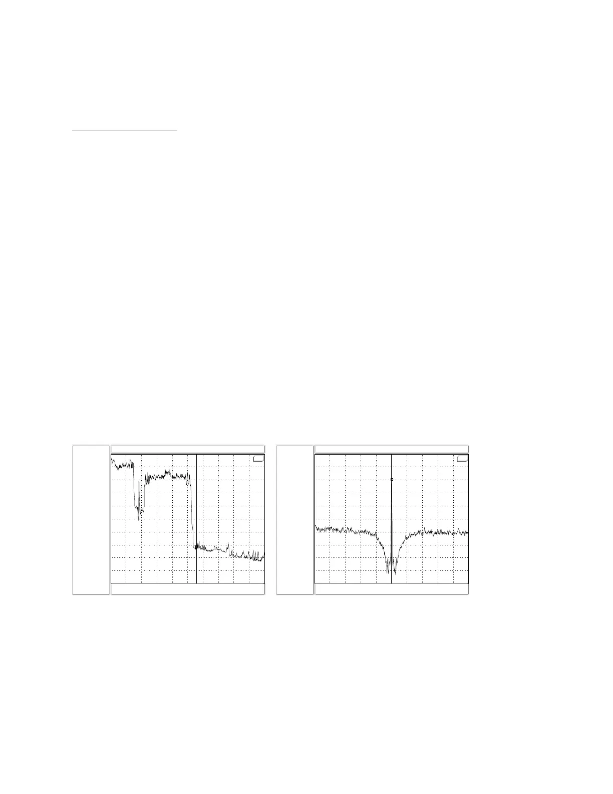
If you are looking at the entire baseband on a spectrum analyzer with a 0-100 kHz sweep,
you may be unable to see the effect of the pilot filter. This is because the filter protects
the pilot ±250 Hz from 19 kHz and the spectrum analyzer will not resolve this when
looking at the entire stereo baseband. To see the filter’s effect, zoom the spectrum ana-
lyzer in to examine only the area immediately around 19 kHz. (Fig. 3-1).
SRS
57.088 kHz -72.881 dBVpk
0 Hz
FFT 1 Log Mag BMH PkhAvg 20000
51.2 kHz 102.4 kHz
-100
dBVpk
0
dBVpk
10
dB/div
Fig. 3-1: 0-100 kHz Baseband Spectrum
(Loud-Hot preset)
SRS
19 kHz -20.643 dBVpk
15.8 kHz
FFT 1 Log Mag BMH PkhAvg 869
19 kHz 22.2 kHz
-100
dBVpk
0
dBVpk
10
dB/div
Fig. 3-2: 19 kHz Pilot Notch Filter Spectrum
(Loud-Hot preset; detail)
We believe that ±250 Hz is a good compromise between excessive width
(which would cause overshoot) and insufficient protection. ±250 Hz is suffi-
cient to protect the phase-locked loops used in most stereo decoders. There