EasyManua.ls Logo

Panasonic AFPX-C30T - Page 255

Panasonic AFPX-C30T
544 pages
To Next Page IconTo Next Page
To Previous Page IconTo Previous Page
Loading...
0 V to 10 V output
Conversion characteristics graph
Table of D/A converted values
Digital input value
Output voltage (V)
0
0.0
400
1.0
800
2.0
1200
3.0
1600
4.0
2000
5.0
2400
6.0
2800
7.0
3200
8.0
3600
9.0
4000
10.0
When exceeding the rated range
Digital input value
Analog output value
Negative value
Unchanged
(Value preceding the input of a negative value)
4001 or more
Unchanged
(Value preceding the input of 4001)
Each channel data is allocated as I/O data as shown below.
Analog output cassette
Output channel
Installed slot No.
Cassette mounting part 1
(Slot 0)
Cassette mounting part 2
(Slot 1)
CH0
WY10
WY20
Note:
Use double-core twisted-pair shielded wires. It is recommended to ground them. However, depending
on the conditions of the external noise, it may be better not to ground the shielding.
Do not have the analog output wiring close to AC wires, power wires, or load.
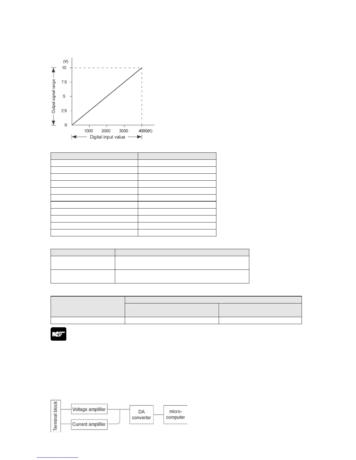
DA part Internal block diagram
A voltage amplifier and a current amplifier is connected in parallel to one DA converter IC.
Do not connect an analog device to the voltage output terminal and current output terminal of the same
channel simultaneously.
Phone: 800.894.0412 - Fax: 888.723.4773 - Web: www.clrwtr.com - Email: info@clrwtr.com

Table of Contents

Related product manuals