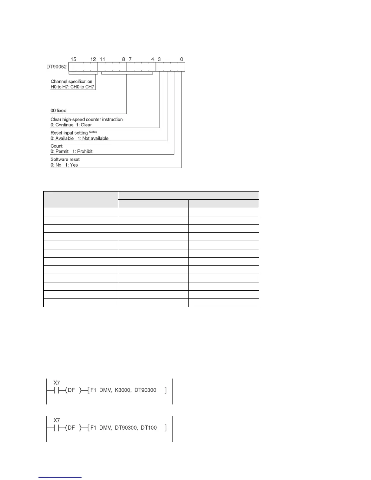
High-speed counter/pulse output control flag area of FP-X Tr type
• The area DT90052 for writing channels
and control codes is allocated as shown in
the left figure.
• Control codes written with an F0 (MV)
instruction are stored by channel in
special data registers DT90370 to
DT90377.
Note)
• In the reset input setting, the reset input
(X6 or X7) for CH0 or CH2 allocated in the
high-speed counter setting of the system
registers are defined to “enable/disable”.
• The high-speed counter to be used with
the reset input is CH0 and CH2 only.
High-speed counter control code monitor area
High-speed counter
Control code monitor area
Elapsed value write and read instruction (F1)
• This instruction changes or reads the elapsed value of the high-speed counter.
• Specify this instruction together with the special data register DT90300.
• The elapsed value is stored as 32-bit data in the combined area of special data registers DT90300 and
DT90301.
• Use this F1 (DMV) instruction to set the elapsed value.
Example 1: Writing the elapsed value
Set the initial value of K3000 in the high-speed
counter.
Example 2: Reading the elapsed value
Read the elapsed value of the high-speed
counter and copies it to DT100 and DT101.
Phone: 800.894.0412 - Fax: 888.723.4773 - Web: www.clrwtr.com - Email: info@clrwtr.com
 Loading...