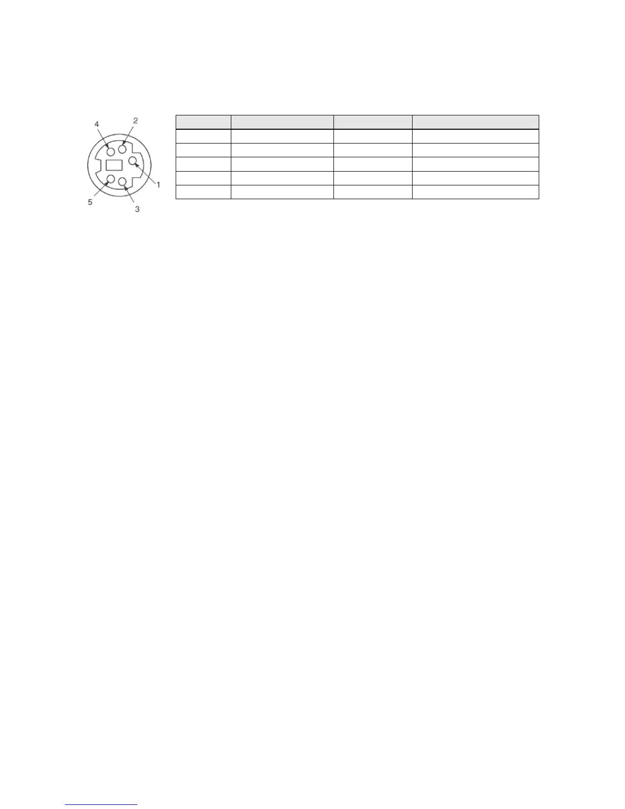
The followings are the default settings set when the unit is shipped from the factory. The system register
“Tool port setting” should be used to change these.
- Baud rate …….. 9600 bps
- Character bit …. 8 bit
- Parity check ….. Odd parity
- Stop bit length .. 1 bit
Note) The unit numbers (station numbers) of the tool port should be specified using the system register
“Tool port setting”.
○
7
Power supply and input terminal block
This is the power supply and input wiring terminal. A solderless terminal for M3 can be used.
○
8
Service power supply for input and output terminal block
This is the service power supply for input and output wiring terminal. A solderless terminal for M3 can be
used.
○
9
Expansion cover
It is used after the expansion cable and the battery has been installed.
○
10
Add-on cassette connector
○
11
Connector For connecting expansion I/O unit and expansion FP0 adapter
An exclusive expansion cable is inserted.
○
12
Battery cover
This battery cover is removed when the optional backup battery is installed.
Installing the backup battery enables the backup of the realtime clock or data registers.
○
13
DIN rail attachment lever
This lever enables the units to attach to a DIN rail at a touch.




 To Next Page