PACD011001C2 Test Operation
Test Operation Urban Multi “MX1, ME1 Series” Using R-22 99
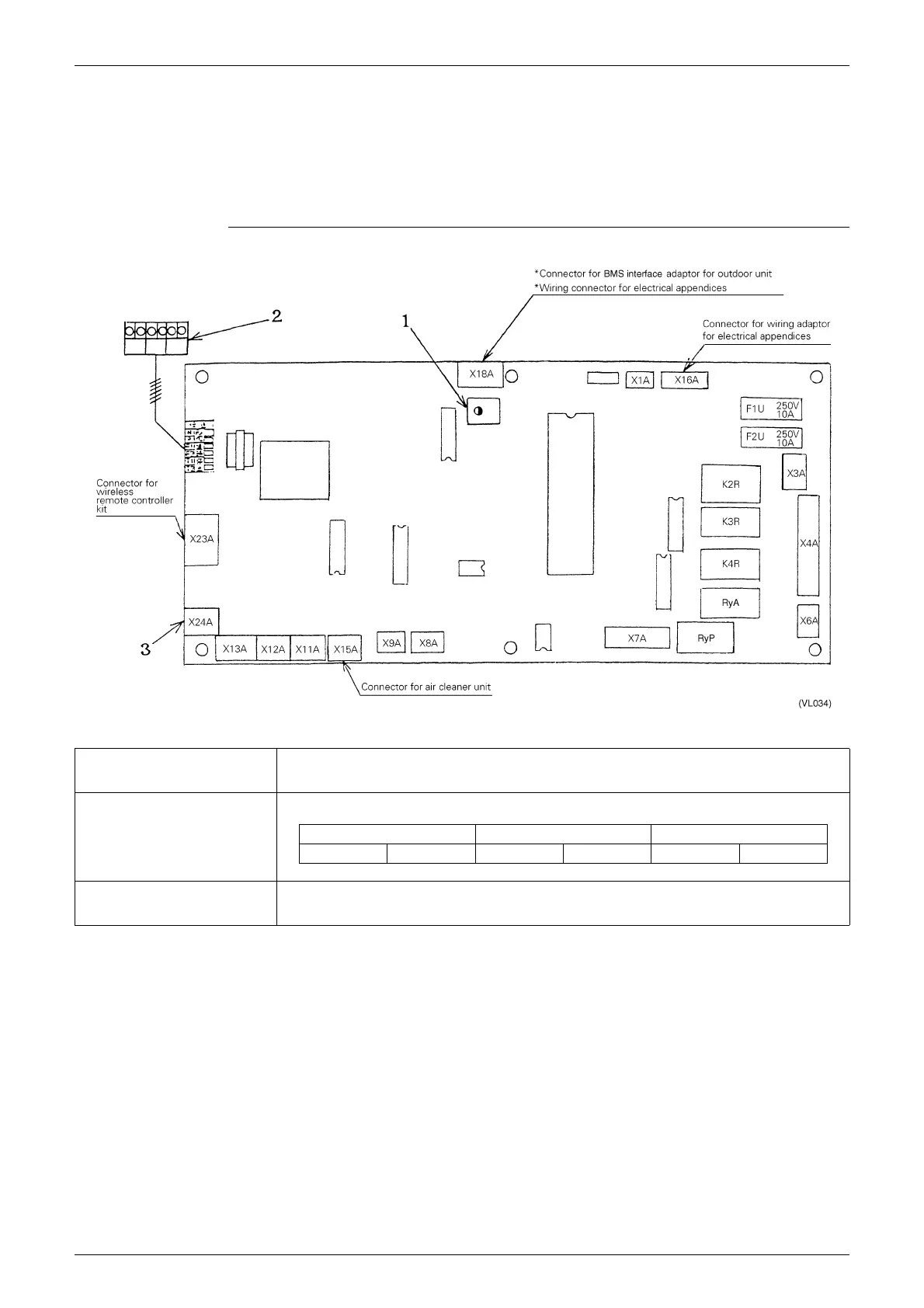
1.15 Indoor Unit PCB Ass’y
The indoor unit PCB ass’y is equipped with terminals for control wiring and connectors for optional control
accessories .
Group No. setting for central control and various operation setting switches, etc., are set by indoor unit
remote controller.
2-way Cassette Type : CS-LM
1 Service Monitor [HAP] (Green) Lets you check the function status of the microcomputer.
Normal : Flicker
Malfunction : On or Off
2 Transmission wiring terminal Terminal for remote controller wiring, indoor - outdoor unit transmission wiring (central wiring), and wiring
for outside input
Remote controller Transmission wiring Outside input
P1 P2 F1 F2 T1 T2
3 Connector for capacity setting
adaptor
Connector for inserting the capacity setting adaptor for when replacing with auxiliary PC board. The
adaptor is required for all models.
∗
Fan phase control for CS-UM, CS-TM and CS-KM only.