30
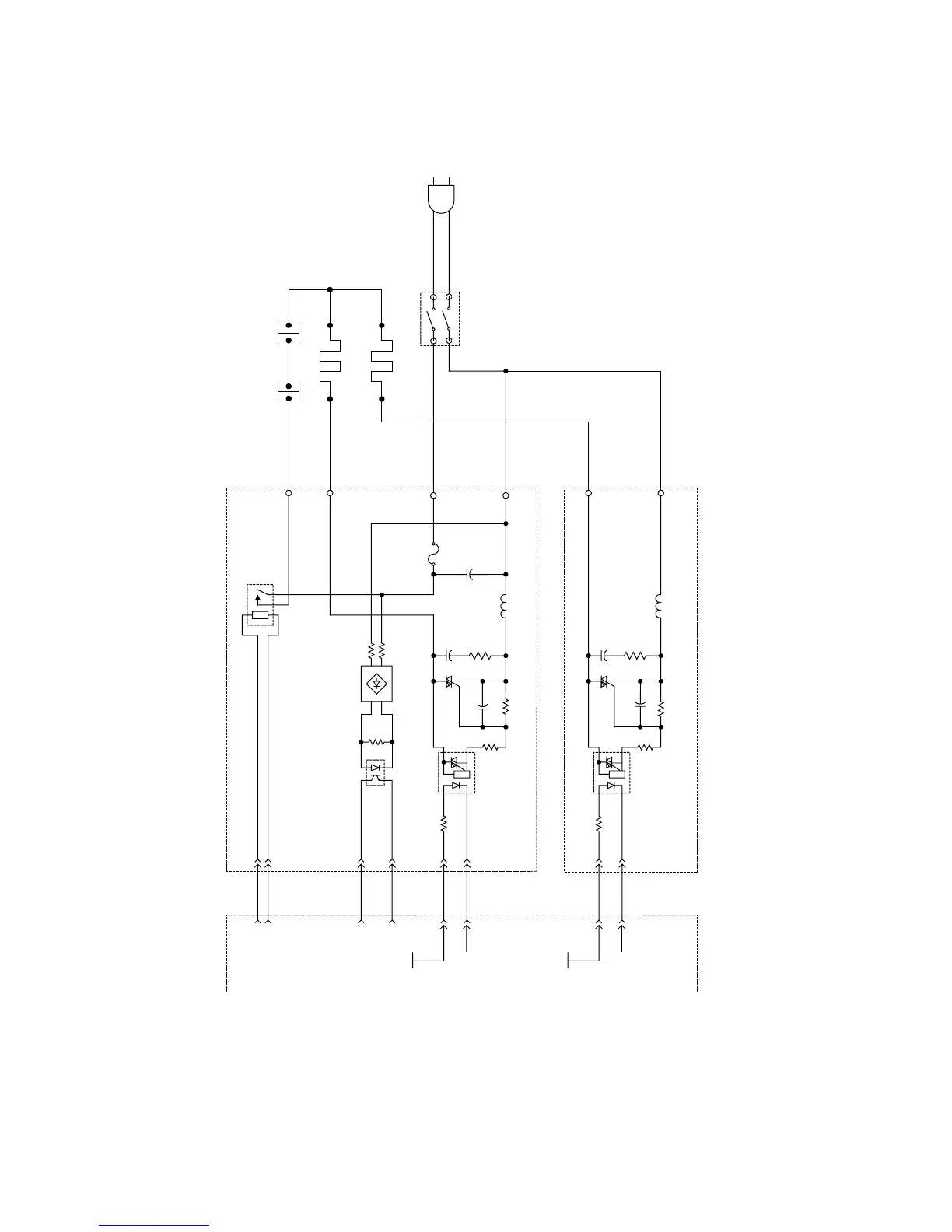
4. Fuser Lamp Drive Circuit
It consists of 2 Fuser Lamps and each Fuser Lamp is controlled by two HTC PC Boards.
The Fuser Lamp is powered by 100 VAC. When the CN765, Pin 6 (nSSR) on the HTC PCB goes LOW,
the Fuser Lamp turns ON. This lights up the PC101 LED and activates the SCR101 photo-triac, and
100 VAC is sent to the Fuser Lamp.
~
~
-
+
ACSW
CN760
CN761
CN764
1
2
CN766
CN767
F101
C101
L101
C102
R101
SCR101
C103
R102
(LPC PCB) (HTC 2 PCB)
(HTC 1 PCB)
Fuser Lamp 2
Fuser Lamp 1
(Outside 850W)
FuseThermostat
(Inside 400W)
PC101
R104
C102
R101
SCR101
C103
R102
R103
R103
L101
PC101
R104
D101
R107
PC102
R105
R106
RL101
CN708
1
2
3
4
5
6
4
3
CN768
4
5
6
7
8
9
CN732
3
4
CN765
+5V
nSSR1
+5V
nSSR2