31
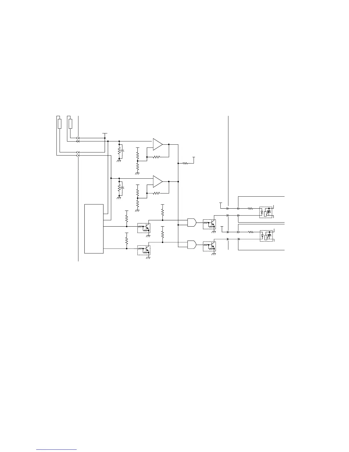
5. Fuser Temperature Control Circuit
The fuser temperature is controlled by IC101 on the LPC PC Board, which contains A/D (Analog/
Digital) converters. IC101 adjusts temperature, observing two Thermistors and voltages separated by
R418 and R439 with A/D converters. When the PC101 drive current is transmitted from the LPC PC
Board to the HTC PCB, the Fuser Lamp turns ON. IC401 is a converter with open output at pins 1 and
7 and is used as an abnormal temperature detection circuit. IC401, pin 1 and 7, has a high impedance
when Q407 and Q413 are activated, turning ON the Fuser Lamp. An abnormal temperature is detected
when the VTH voltage level becomes higher than V+, forcing IC401, pin 1 and 7 Low and
deactivating Q407 and Q413.
Abnormally low and high temperatures, as well as Thermistor release status, are detected by IC101
(CPU) programming.
+5V
C402
R418
Thermistor
Thermistor
+5V
+
-
R417
R416
R415
IC401
C418
+5V
+
-
R441
R440
R442
IC401
R439
+5V
+5V
+5V
+5V
PC101
R104
5
6
PC101
R104
5
6
+5V
+5V
+5V
R448
IC404
IC404
Q407
Q413
R450
R451
Q408
Q414
IC101
(LPC PCB)
(HTC 1 PCB)
(HTC 2 PCB)
Fuser Temperature Control Circuit
CN765
CN765
CN708
8
9
CN732
3
4
CN716
1
2
3
4
VTH
V+
VTH
V+
R449R419
7
6
5
1
2
3