33
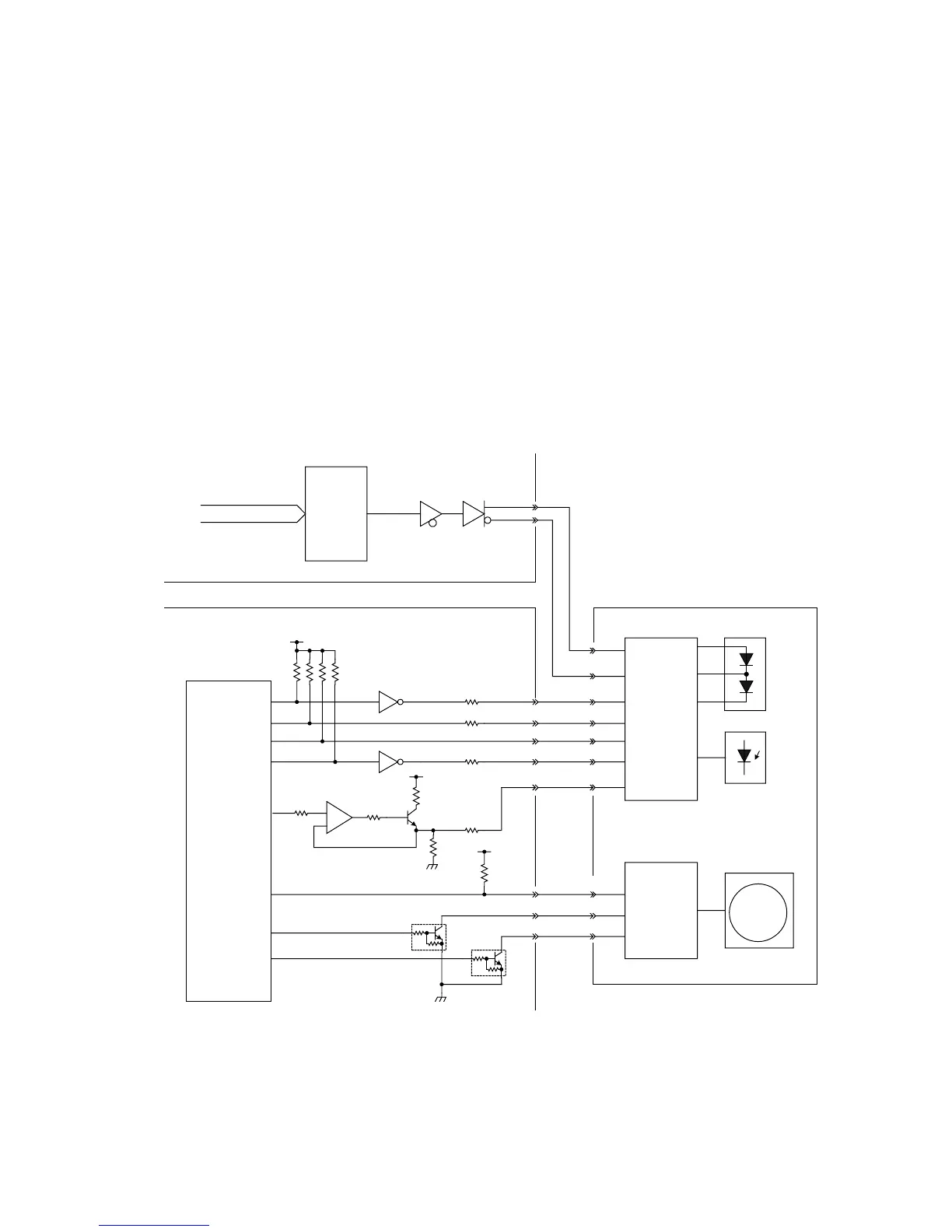
7. LSU Control Circuit
The laser control signals are described below.
Actual data is sent from SC PCB to LSU.
VIDEO+ : Actual data is outputted by these 2 signals.
VIDEO-
nS/H : Laser Power Sample/Hold Timing Signal.
nHSYNC : This horizontal synchronization signal transmitted from the Beam Detection Sen-
sor sets the horizontal position of the laser beam as it crosses the OPC Drum.
nLDON : The LSU is activated when this output signal is LOW. If an error occurs, the
nLDON output signal level goes High and the LSU is deactivated.
pLDCTL : This signal turns ON the laser output to activate nHSYNC signal.
VCON : This is the Analog Voltage for adjusting Laser output power.
nPMCK : This is the Polygon Motor Drive Clock.
nPMRDY : When the Polygon Motor speed is constant, the nPMRDY is at a Low output sig-
nal level.
nPMON : This is the Polygon Motor Control Signal. The Polygon Motor rotates when the
nPMON output signal level is LOW.
+5V
IC46
IC47
SC PCB
LPC PCB
IC49
IC101
CPU
R331
R358
R333
IC702
IC702
IC701
R365
R369
R371
R370
R364
Q304
Q305
CN701
1
6
2
5
8
R335
11
9
10
nS/H
nHSYNC
nLDON
pLDCTL
VCONT
3
4
VIDEO+
VIDEO-
nPMCK
nPMRDY
nPMCK
nPMON
VIDEO DATA
Laser
Control
Circuit
Motor
Drive
Circuit
Laser Unit (LSU)
Laser
Timing
Sensor
Scanner
Motor