FPΣ User's Manual
7.2 Function Specifications and Restrictions
103
Related instructions
F166_HighSpeedCounter_Set: Target value match ON
F167_HighSpeedCounter_Reset: Target value match OFF
Specify the desired output from Y0 to Y7 using the instructions.
7.2.2 Pulse Output Function
For each pulse output mode and position control mode there are certain designated high-
speed counter channels, inputs and outputs.
NOTE
• The pulse output function is only available with the transistor output type.
• Linear and circular interpolation control is only available with CPU type
C32T2(TM) and C28P2(TM).
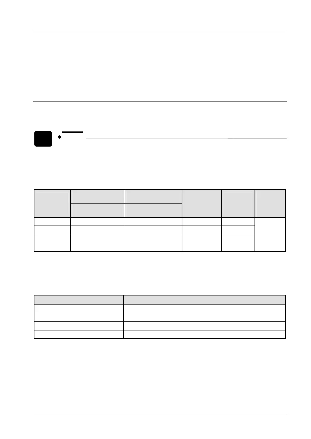
Input/output numbers
CW pulse output CCW pulse output
Channel
no.
Pulse output Direction output
Deviation
counter
clear output
Home
input
Near
home
input
0 Y0 Y1 Y2 X2
2 Y3 Y4 Y5 X5
Interpolation
1)
Y0
Y3
Y1
Y4
Y2
Y5
X2
X5
Any
2)
1)
The home return operation of the interpolation axes should be performed for every channel (see page
145).
2)
Any input can be specified in the global variable list. The near home input is enabled/disabled using the
pulse output control code. See "
Writing the Pulse Output Control Code" on page 126.
Performance
No. of channels Maximum output frequency
1
100kHz (×1 channel)
2
60kHz (×2 channels)
Linear interpolation control 100kHz
Circular interpolation control 20kHz
Control flags and memory areas
Counter and pulse output settings as well as elapsed values are stored in special data
registers. The pulse output status is stored in special internal relays. To access special data
registers and special internal relays, use the PLC-independent system variables. You can
insert system variables directly into the POU body: Use the "Variables" dialog without entering
a declaration in the POU header. See "
Instructions and system variables" on page 124.
 Loading...