FPΣ User's Manual
7.3 High-Speed Counter Function
109
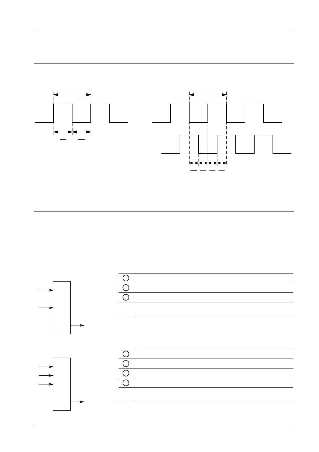
7.3.2 Minimum Input Pulse Width
For the period T (1/frequency), a minimum input pulse width of T/2 (single-phase input) or T/4
(two-phase input) is required.
T
T
2
T
2
T
4
T
T
4
T
4
T
4
Single-phase input Two-phase input
7.3.3 I/O Allocation
The inputs and outputs used will differ depending on the channel number being used. (See
"
Function Specifications and Restrictions" on page 102.)
The output to be turned to TRUE or to FALSE can be specified with the instructions
F166_HighSpeedCounter_Set and F167_HighSpeedCounter_Reset. Outputs can be
specified from Y0 to Y7.
Using channel 0 with incremental input and reset input
1
Count input X0
2
Reset input X2
3
TRUE/FALSE output
Yn
The output which is turned TRUE or FALSE when the target value is
reached: Y0–Y7
FPΣ:
Using channel 0 with two-phase input and reset input
1
Phase A input X0
2
Phase B input X1
3
Reset input X2
4
TRUE/FALSE output
Yn
The output which is turned TRUE or FALSE when the target value is
reached: Y0–Y7
FPΣ:
 Loading...