Appendix
FPΣ User's Manual
284
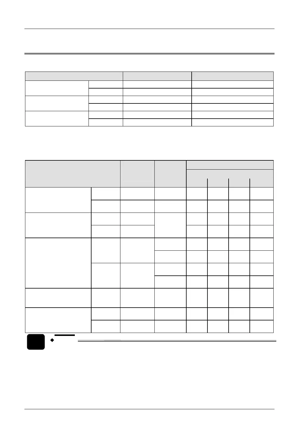
12.3 I/O Allocation
FPΣ CPUs
CPU type Number of I/O points I/O addresses
Input 16 X0–XF
FPG-C32x (NPN)
Output 16 Y0–YF
Input 16 X0–XF
FPG-C28x (PNP)
Output 12 Y0–YB
Input 16 X0–XF
FPG-C24x (Relay)
Output 8 Y0–Y7
FPΣ expansion units (left side expansion)
I/O allocation is performed automatically when an expansion unit is added and is determined
by the installation location.
I/O addresses
[Unit number/Slot number]
Type of unit
Number of
I/O points
Axis
1/0 2/1 3/2 4/3
Input 32 –
X100–
X11F
X180–
X19F
X260–
X27F
X340–
X35F
FPΣ I/O expansion unit
FPG-XY64D2T,
FPG-XY64D2P
Output 32 –
Y100–
Y11F
Y180–
Y19F
Y260–
Y27F
Y340–
Y35F
Input 16
X100–
X10F
X180–
X18F
X260–
X26F
X340–
X34F
FPΣ positioning unit,
1-axis type
FPG-PP11,
FPG-PP12
Output 16
1st
Y100–
Y10F
Y180–
Y18F
Y260–
Y26F
Y340–
Y34F
1st
X100–
X10F
X180–
X18F
X260–
X26F
X340–
X34F
Input 32
2nd
X110–
X11F
X190–
X19F
X270–
X27F
X350–
X35F
1st
Y100–
Y10F
Y180–
Y18F
Y260–
Y26F
Y340–
Y34F
FPΣ positioning unit,
2-axis type
FPG-PP21,
FPG-PP22
Output 32
2nd
Y110–
Y11F
Y190–
Y19F
Y270–
Y27F
Y350–
Y35F
FPΣ memory expansion
unit
FPG-EM1
Input
(Battery
error)
16 –
X100–
X10F
X180–
X18F
X260–
X26F
X340–
X34F
Input 128 –
X100–
X17F
X180–
X25F
X260–
X33F
X340–
X41F
FPΣ S-Link master unit
FPG-SL
Output 128 –
Y100–
Y17F
Y180–
Y25F
Y260–
Y33F
Y340–
Y41F
NOTE
• Regarding I/O allocation of the FPΣ Positioning Unit RTEX, please refer to
the Technical Manual of this unit.
 Loading...