FPΣ User's Manual
3.4 Analog Potentiometer
29
3.4 Analog Potentiometer
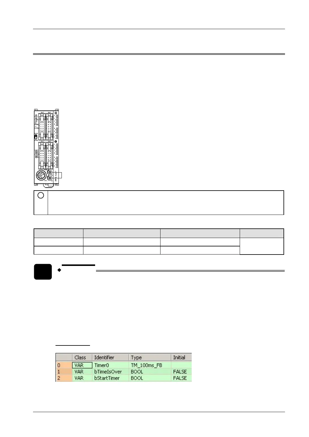
The FPΣ is equipped with two analog potentiometers. Turning the potentiometers changes the
values of the special data registers reserved for the potentiometer input. The values can be
set within a range of 0-1000.
Using the potentiometers, you can change the internal set values in the PLC (e.g. of an
analog clock) without needing the programming tool. To access special data registers and
special internal relays, use the PLC-independent system variables.
1
Analog potentiometers
V0 (potentiometer 0): Changes the value of DT90040 within a range of 0 to 1000.
V1 (potentiometer 1): Changes the value of DT90041 within a range of 0 to 1000.
System variables and special data registers
Potentiometer System variable Special data register Range
V0
sys_iPotiInputV0 DT90040
V1
sys_iPotiInputV1 DT90041
0–1000
EXAMPLE
In this example, an analog clock is created that allows you to set the time via a
potentiometer. The value of special data register DT90040 set using V0 is used as a
set value for a timer. This value is written into the set value area (SV) of Timer0 to set
the clock. The value of DT90040 is read using the system variable sys_iPotiInputV0,
which can be inserted directly into the body via the "Variables" dialog without a
declaration in the POU header. Please refer to the FPWIN Pro online help for detailed
information on using system variables.
POU Header