FPΣ User's Manual
4.2 FPΣ I/O Expansion Units
47
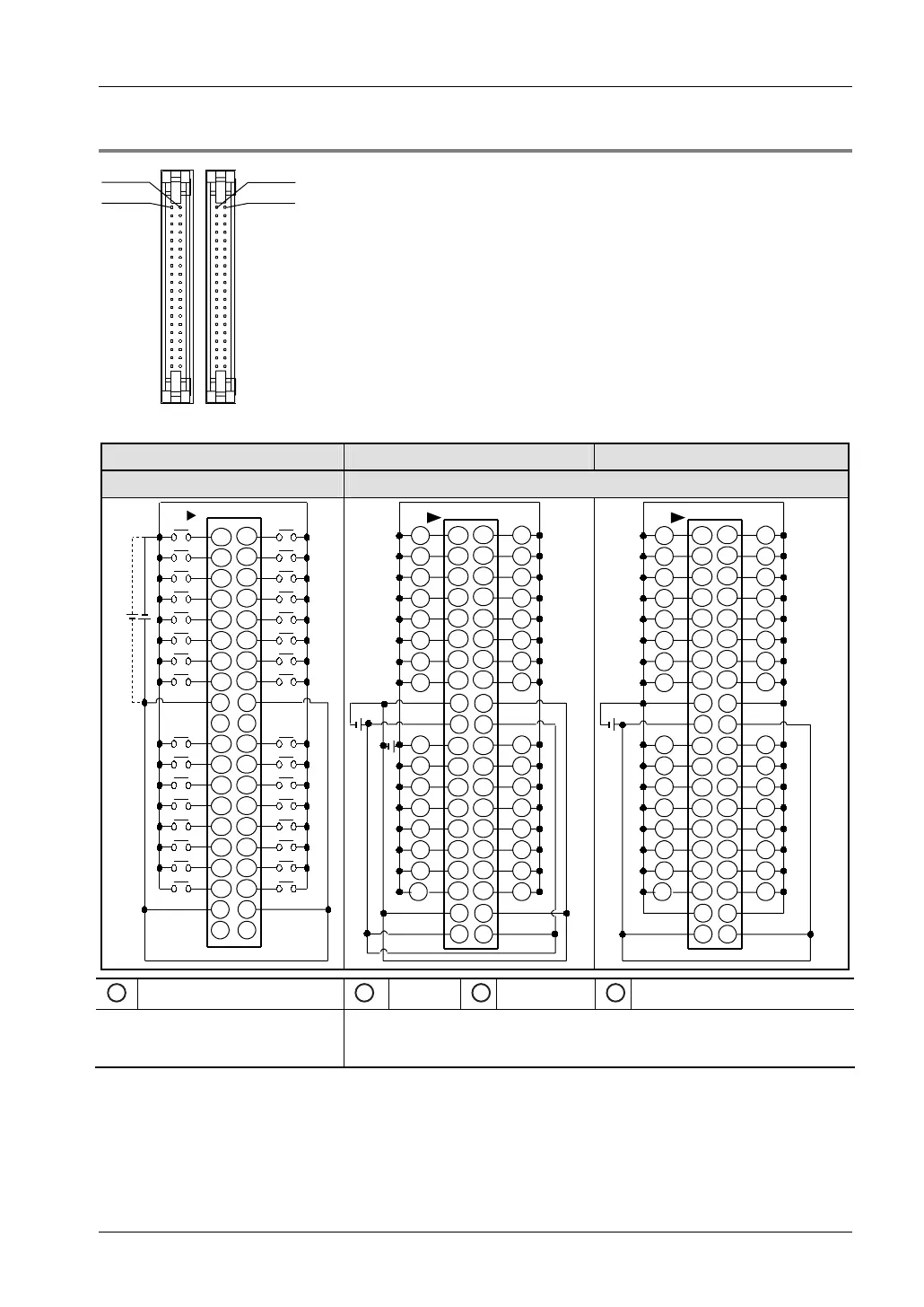
4.2.3 Terminal Layout
X108
X100
Y100
Y108
Connector front view
Input connector Output connector (NPN) Output connector (PNP)
LEFT RIGHT
1 1
2 2
3 3
4 4
5 5
6 6
7 7
8 8
COM
99
N.C.
11 11
12 12
13 13
14 14
15
15
16 16
17 17
18 18
COM
19 19
N.C.
20
N.C.
20
COM
AB
N.C.
COM
10 10
110
111
112
113
114
115
116
117
118
119
11A
11B
11C
11D
11E
11F
100
10D
10C
101
102
103
104
105
106
107
108
109
10A
10B
10F
10E
1
AB
1
22
33
44
55
66
77
88
9 9
10 10
11 11
12 12
13 13
14 14
15 15
16 16
17 17
18 18
19
–
19
+
20
+
20
L
L
L
L
L
L
L
L
L
L
L
L
L
L
L
L
L
L
L
L
L
L
L
L
L
L
L
L
L
L
L
L
100
10D
10C
101
102
103
104
105
106
107
108
109
10A
10B
10F
10E
110
111
112
113
114
115
116
117
118
119
11A
11B
11C
11D
11E
11F
–
–
++
–
1
AB
1
22
33
44
55
66
77
88
9 9
10 10
11 11
12 12
13 13
14 14
15 15
16 16
17 17
18 18
19
–
19
+
20
+
20
L
L
L
L
L
L
L
L
L
L
L
L
L
L
L
L
L
L
L
L
L
L
L
L
L
L
L
L
L
L
L
L
100
10D
10C
101
102
103
104
105
106
107
108
109
10A
10B
10F
10E
110
111
112
113
114
115
116
117
118
119
11A
11B
11C
11D
11E
11F
–
––
++
1
24V DC
1
24V DC
2
5–24V DC
1
24V DC
The COM terminals of the input
circuits are connected internally.
The (+) terminals as well as the (-) terminals of the output circuits are
connected internally. It is recommended to connect the terminals also
externally.