FPΣ User's Manual
8.6 Program Controlled Communication
221
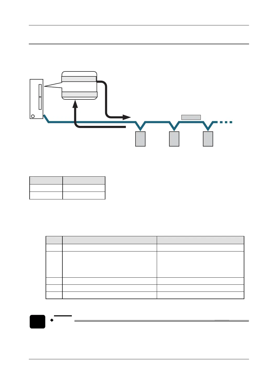
8.6.7 1:N Communication
The FPΣ and the external units are connected using an RS485 cable. Using the protocol that
matches the external units, the F159_MTRN instruction is used to send and receive data.
RS485
Data registers (DT)
Data to be sent
Data received
Data is sent using F159_MTRN
Data is received in receive buffer
PLC
The RS485 port of FPG-COM4 occupies the communication line for a certain period of time
after sending data. During this time, data cannot be received from another device. Therefore,
the connected device should not send a response to the FPΣ before the time t indicated below
has passed.
Baud rate Response time
19200bit/s t > 1ms
115200bit/s
t > 200μs
System register settings
By default, the COM port is set to MEWTOCOL-COM mode. For 1:N program controlled
communication, the system registers should be set as shown below.
• Settings for COM port 1 (FPG-COM3, FPG-COM4)
No. Name Set value
412
COM port 1 - communication mode Program controlled
413 COM port 1 - communication format
*)
Data length: 7 bits/8 bits
Parity: None/Odd/Even
Stop bit: 1 bit/2 bits
End code: CR/CR+LF/None/ETX
Start code: No STX/STX
415
COM port 1 - baud rate
*)
2400–115200bit/s
416
COM port 1 - receive buffer starting address 0–32762 (initial value: 0)
417
COM port 1 - receive buffer capacity 0–2048 words (initial value: 2048 words)
*)
The setting must match the external device connected to the communication port.
NOTE
• When the RS485 port (COM port 1) of FPG-COM4 is used, set the baud rate
in the system registers to either 19200bit/s or 115200bit/s. Set DIP switch
SW1-2 of the cassette to the same setting (see page
162).
 Loading...