FPΣ User's Manual
7.4 Pulse Output Function
123
7.4.2 I/O Allocation
The I/O allocation of pulse output terminals, direction output terminal, and home input is
determined by the channel used.
For the near home input, the desired contact must be allocated and bit 4 of the special data
register storing the pulse output control code (sys_wHscOrPulseControlCode) must be set to
TRUE and back to FALSE again.
REFERENCE
The input/output numbers are indicated by channel in the specifications. See
"
Pulse Output Function" on page 103.
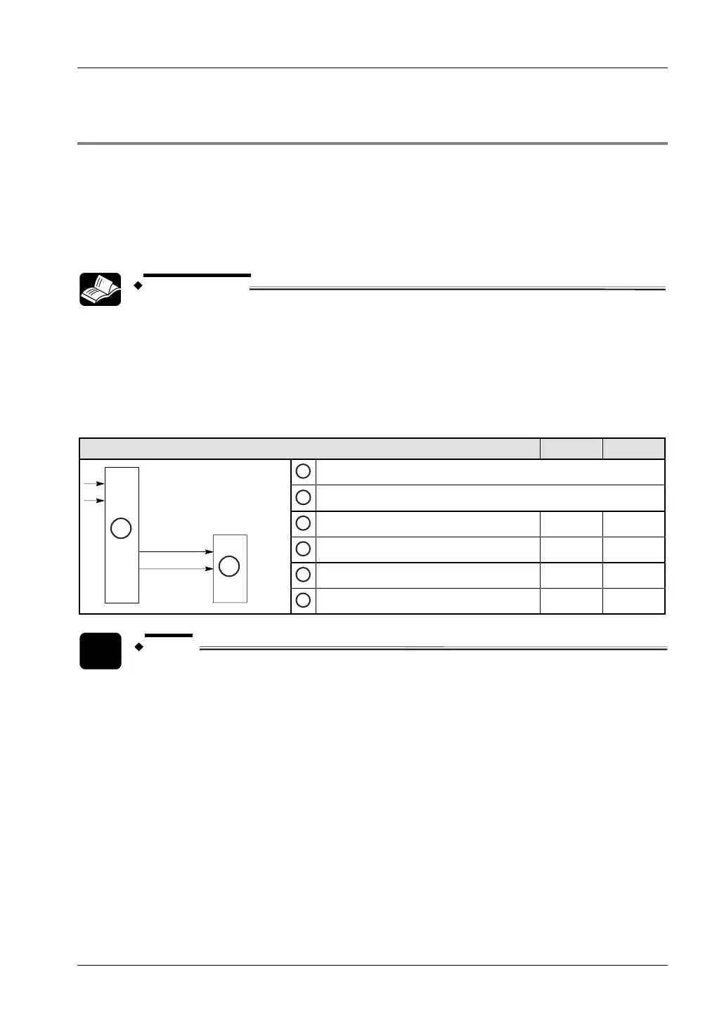
Double pulse input driver (CW/CCW pulse output method)
Two output contacts are used as a pulse output for CW/CCW.
Set the control code for F171_SPDH to CW/CCW.
Using channel 0 2
A
PLC
B
Motor driver
1
Home input X2 X5
2
Near home input (see note) e.g. X3 e.g. X6
3
CW pulse output Y0 Y3
A
B
4
CCW pulse output Y1 Y4
NOTE
Any input that is not used for other applications can be used as the near home
input.
Single pulse input driver (pulse and direction output method)
One output point is used as the pulse output and the other output is used as the direction
output.
Set the control code for F171_SPDH to pulse and direction.
Up to two driver systems can be connected.
 Loading...