33
9 Service Position
Note: For description of the disassembly procedures, refer
Section 8 of the Service Manual.
9.1. Checking of FL Display P.C.B.,
Button Left P.C.B., Button
Right P.C.B. and Multi Control
P. C. B.
Step 1 Remove Top Cabinet.
Step 2 Remove Front Panel Unit.
Step 3 Remove Fan Unit.
Step 4 Remove FL Display P.C.B..
Step 5 Remove Illumination Button P.C.B..
Step 6 Remove BT&NFC P.C.B.
Step 7 Remove DJ Cabinet Unit.
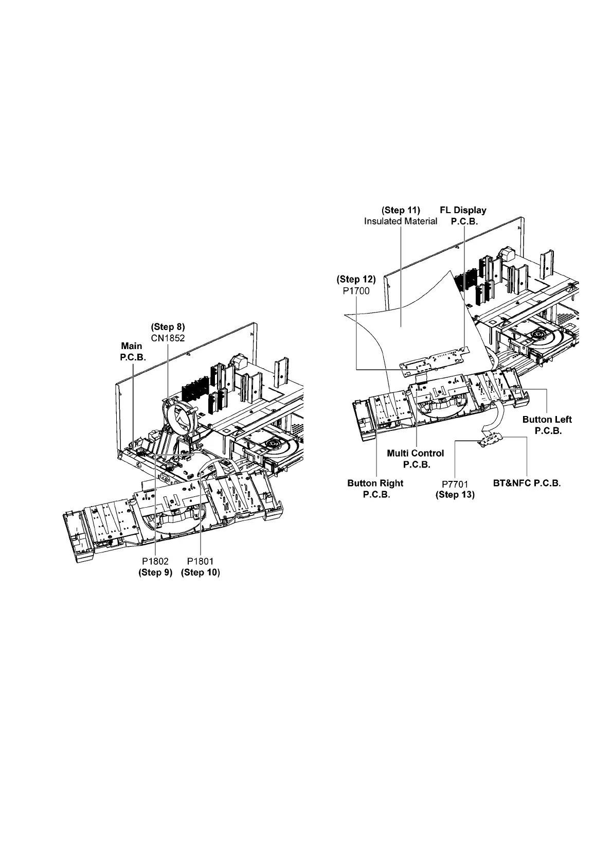
Step 8 Attach 2P Wire at connector (CN1852) on SMPS P.C.B..
Step 9 Attach 30P FFC at connector (P1802) on Main P.C.B..
Step 10 Attach 14P FFC at connector (P1801) on Main P.C.B..
Step 11 Place FL Display P.C.B. on the insulated material as
shown.
Step 12 Attach 13P FFC at connector (P1700) on FL Display
P. C .B ..
Step 13 Attach 12P FFC at connector (P7701) on BT&NFC
P. C .B .
Step 14 FL Display P.C.B., Button Left P.C.B., Button Right
P.C.B. and Multi Control P.C.B. can be checked as diagram
shown.