34
9.2. Checking of SMPS P.C.B.
Step 1 Remove Top Cabinet.
Step 2 Remove Front Panel Unit.
Step 3 Remove Fan Unit.
Step 4 Remove SMPS P.C.B..
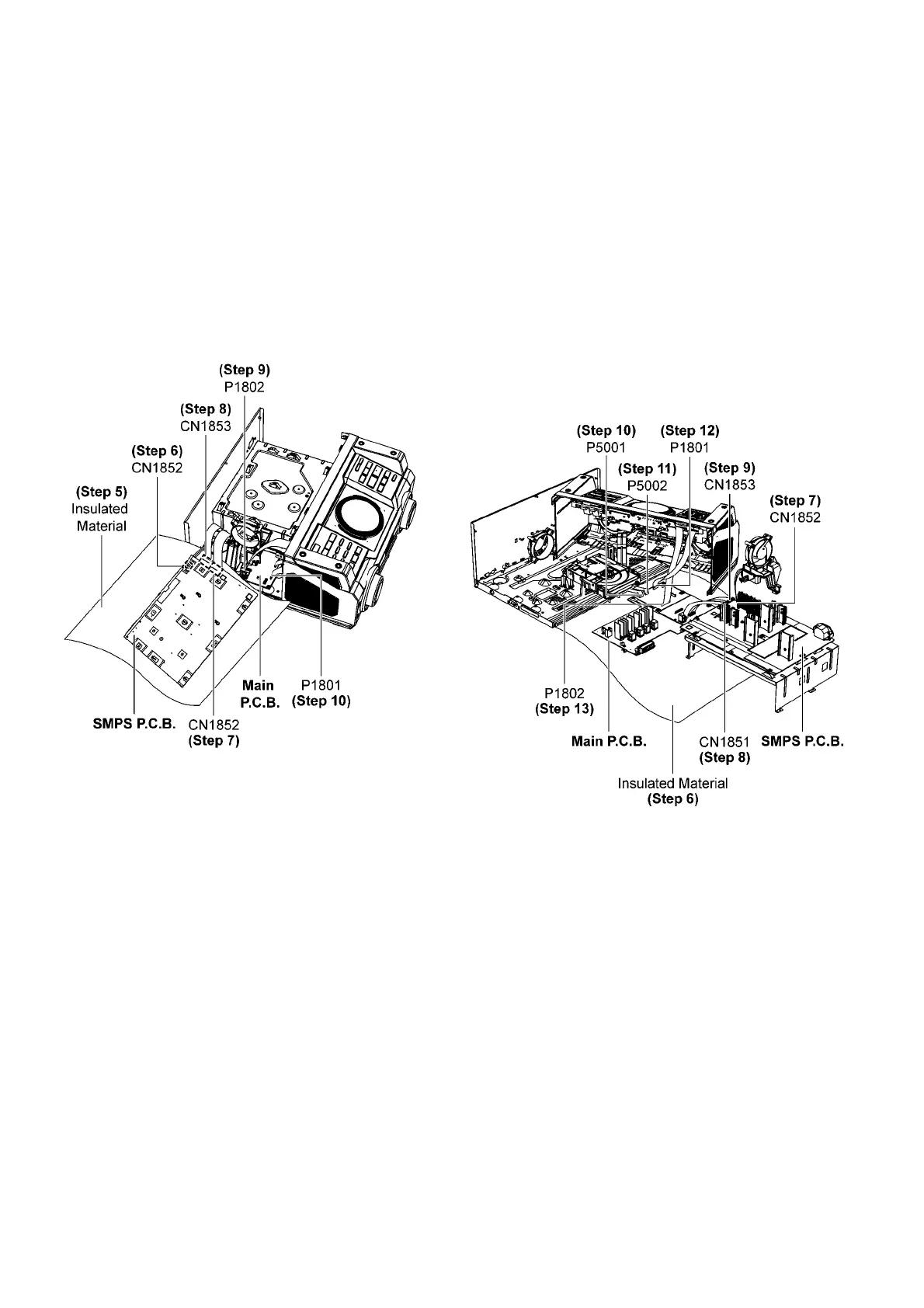
Step 5 Place SMPS P.C.B. on the insulated material as shown.
Step 6 Attach 2P Wire at connector (CN1852) on SMPS P.C.B..
Step 7 Attach 13P Wire at connector (CN1851) on SMPS
P.C .B..
Step 8 Attach 10P Wire at connector (CN1853) on SMPS
P.C .B..
Step 9 Attach 30P FFC at connector (P1802) on Main P.C.B..
Step 10 Attach 14P FFC at connector (P1801) on Main P.C.B..
Step 11 SMPS P.C.B. can be checked as diagram shown.
9.3. Checking of Main P.C.B.
Step 1 Remove Top Cabinet.
Step 2 Remove Front Panel Unit.
Step 3 Remove Fan Unit.
Step 4 Remove Inner Chassis Unit.
Step 5 Remove Main P.C.B..
Step 6 Place Main P.C.B. on the insulated material as shown.
Step 7 Attach 2P Wire at connector (CN1852) on SMPS P.C.B..
Step 8 Attach 13P Wire at connector (CN1851) on SMPS
P.C .B..
Step 9 Attach 10P Wire at connector (CN1853) on SMPS
P.C .B..
Step 10 Attach 10P FFC at connector (P5001) on Main P.C.B..
Step 11 Attach 24P FFC at connector (P5002) on Main P.C.B..
Step 12 Attach 14P FFC at connector (P1801) on Main P.C.B..
Step 13 Attach 30P FFC at connector (P1802) on Main P.C.B..
Step 14 Main P.C.B. can be checked as diagram shown.