45
12 Schematic Diagram
12.1. Schematic Diagram Notes
• This schematic diagram may be modified at any time
with the development of new technology.
Notes:
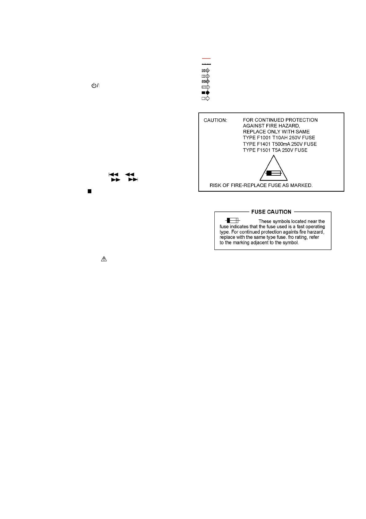
• Important safety notice:
Components identified by mark have special characteris-
tics important for safety.
Furthermore, special parts which have purposes of fire-retar-
dant (resistors), high quality sound (capacitors), low-noise
(resistors), etc are used.
When replacing any of components, be sure to use only
manufacturer’s specified parts shown in the parts list.
• In case of AC rated voltage Capacitors, the part no. and val-
ues will be indicated in the Schematic Diagram.
AC rated voltage capacitors:
C1001, C1002, C1003, C1004, C1006, C1518
• Resistor
Unit of resistance is OHM [Ω] (K=1,000, M=1,000,000).
• Capacitor
Unit of capacitance is μF, unless otherwise noted. F=Farads,
pF=pico-Farad.
• Coil
Unit of inductance is H, unless otherwise noted.
•
*
REF IS FOR INDICATION ONLY.
• Voltage and signal line
S1500:
Power ( ) switch.
S1501: Manual EQ switch.
S1502: Latin Preset EQ switch.
S1503: D.BASS/-Superwoofer switch.
S1504: Memory 3 switch.
S1505: Memory 2 switch.
S1506: Memory 1 switch.
S1507: Memory 5 switch.
S1508: Memory 4 switch.
S1509: Memory 6 switch.
S1510: DJ Effect switch.
S1511: DJ Sampler switch.
S1512: DJ Jukebox switch.
S1650: Open/Close switch.
S1651: USB Rec switch.
S1652: Memory Rec switch.
S1653: Rewind/Skip ( / ) switch.
S1654:
Forward/Skip ( / ) switch.
S1655: Album/Track switch.
S1656: Stop ( ) /Tune switch.
S1657: Bluetooth/Memory switch.
S1658: Playback switch.
S1659: USB/CD switch.
S1660: Radio/EXT-IN switch.
S7201: Reset switch.
VR1401: Mic Jog.
VR1600: Multi Control Jog.
VR1930: Illumination Jog.
VR1960: Volume Jog.
: +B signal line
: -B signal line
: CD Audio input signal line
: Tuner/AUX/Mic input signal line
: Audio output signal line
: USB signal line
: AM signal line
: FM signal line