55
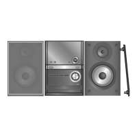
Step 11 : Connect 11P FFC at connector (CN901) on Main
P.C .B. .
Step 12 : Connect 22P FFC at connector (CN380) on USB
P.C .B. .
Step 13 : Connect 4P cable at connector (CN5902) on Trans-
former P.C.B..
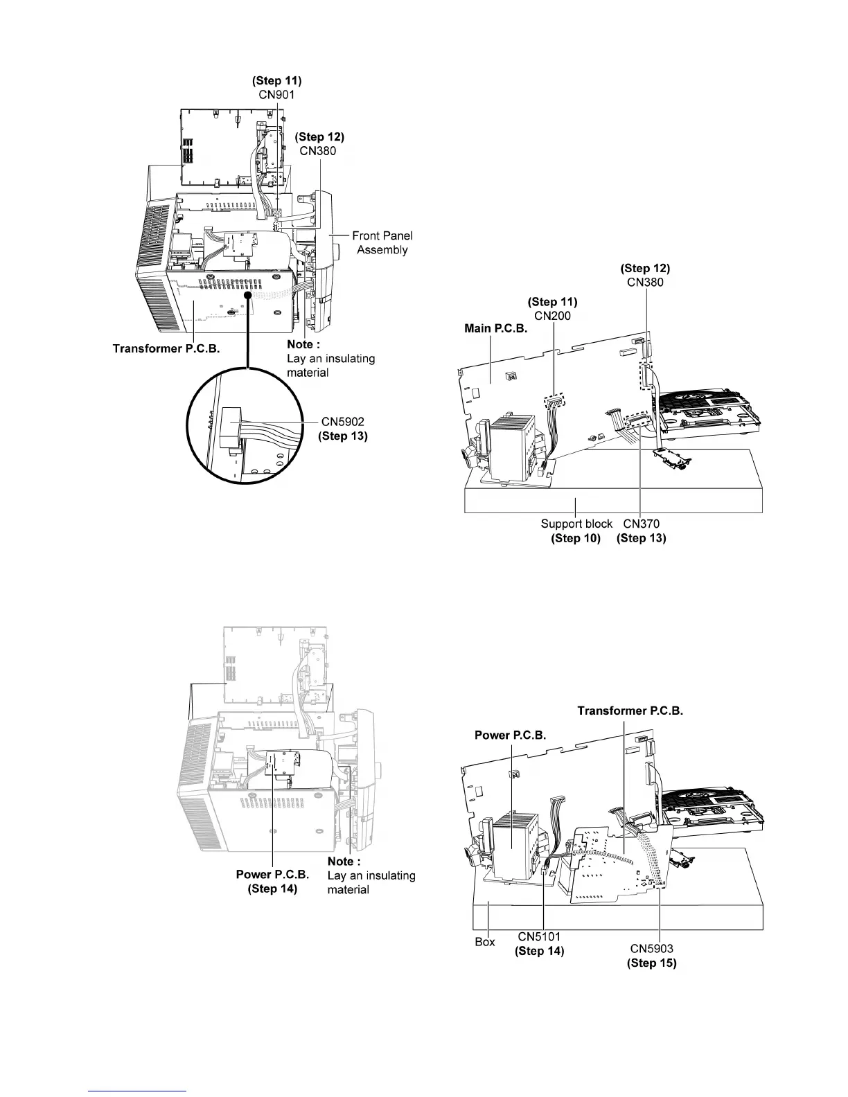
Step 14 : Check & repair Power P.C.B. according to the dia-
gram shown.
12.6. Checking & Repairing Trans-
former P.C.B.
Step 1 : Remove Top Cabinet Assembly.
Step 2 : Remove Front Panel Assembly.
Step 3 : Remove USB P.C.B..
Step 4 : Remove Panel P.C.B..
Step 5 : Remove Power P.C.B..
Step 6 : Remove Main P.C.B..
Step 7 : Remove Transformer P.C.B..
Step 8 : Remove CD Mechanism Unit (DLS6C).
Step 9 : Remove Fan Unit.
Step 10 : Place a support block as diagram shown.
Step 11 : Connect 6P cable at connector (CN200) on Main
P. C .B . .
Step 12 : Connect 22P cable at connector (CN380) on Main
P. C .B . .
Step 13 : Connect 22P cable at connector (CN370) on Main
P. C .B . .
Step 14 : Connect 4P cable at connector (CN5101) on Power
P. C .B . .