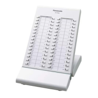
EasyManua.ls Logo

Panasonic WR-DA7 - Meter Bridge

Panasonic WR-DA7
369 pages
Print Icon
To Next Page IconTo Next Page
To Previous Page IconTo Previous Page
Loading...
17-7 METER BRIDGE
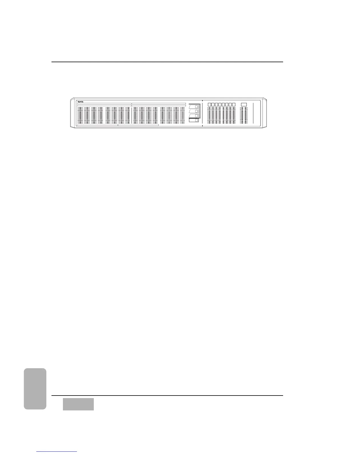
The METER BRIDGE option for the DA7 provides a visual representation of
the [METER] input window. The METER BRIDGE will show the 16 Channel
Meters (1-16 or 17-32), or AUX SNDS 1-6 and AUX RTNS 1-6. The BUS 1-
8 and the MONITOR A L/R outputs are always displayed.
A Fader Layer selection LED pad is built into the METER BRIDGE and
operates the same way as the Fader Layer section on the Top Panel of the
DA7. The CONSOLE LINK LED button when selected (red), links the
METER BRIDGE to follow the Top Panel Fader Layer selection.
See instructions packed with the METER BRIDGE for more information.
Chapter 17
DA7 Users’ Guide
17
-
16
17
Options
BUS
1
INPUT
1-16
INPUT
17-32
AUX
CONSOLE
LINK
BUS
2
BUS
3
BUS
4
BUS
5
BUS
6
BUS
7
BUS
8
MONITOR A
L R
OL
2
4
6
8
10
12
15
18
20
25
30
35
40
50
OL
2
4
6
8
10
12
15
18
20
25
30
35
40
50
OL
2
4
6
8
10
12
15
18
20
25
30
35
40
50
OL
2
4
6
8
10
12
15
18
20
25
30
35
40
50
1
17
2
18
3
19
4
20
5
21
6
22
7
23
8
24
9
25
10
26
11
27
12
28
13
29
14
30
15
31
16
32
SOLT 3
SOLT 2SOLT1
AUX SND 1 AUX SND 2 AUX SND 3 AUX SND 4 AUX SND 5 AUX SND 6 AUX RTN 1 AUX RTN 2 AUX RTN 3 AUX RTN 4 AUX RTN 5 AUX RTN 6
METER BRIDGE

Table of Contents

Other manuals for Panasonic WR-DA7

Related product manuals