Chapter 2
DA7 Users’ Guide
2
-
25
2
DA7 Tour
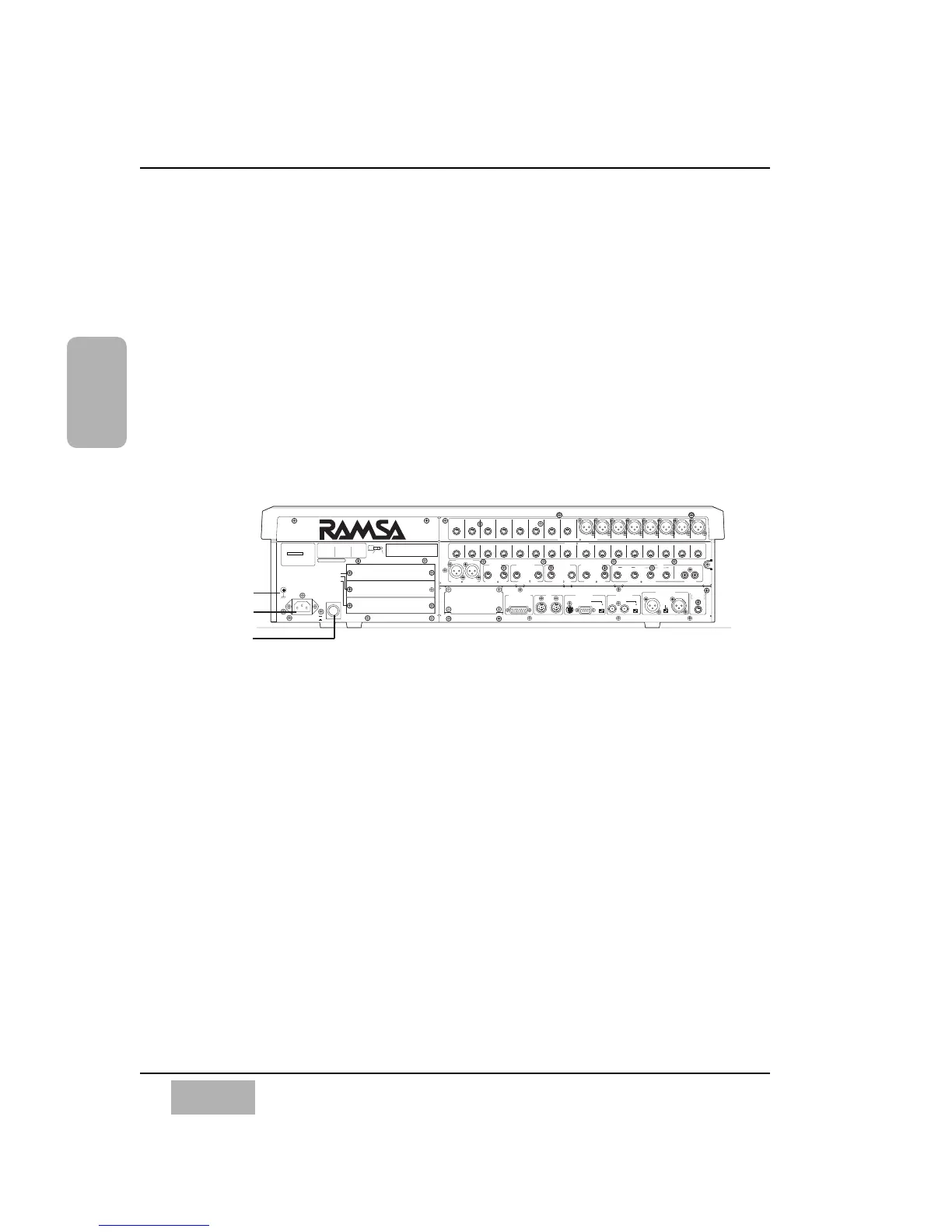
2-4 Rear Panel
Everything that goes in, out, and through the DA7 happens on the Rear
Panel, with the exception of the headphone connector. The DA7 provides
multiple ways for doing many things, so let your creativity be your guide.
The rear of the DA7 is configured in four rows. The top row contains analog
INPUTS 1-16 (inputs 1-8 are balanced XLR connectors and inputs 9-16 are
balanced TRS (tip-ring-sleeve) phone plug connectors). Row 2 contains
analog INS 1-16 (inserts) with (TRS) phone plug connectors. Row 3 contains
outputs for MASTER OUT, REC OUT analog, MONITORS A&B, and AUX
returns and sends 1 through 6. The bottom row contains the METER
BRIDGE connection, MIDI IN/OUT, SERIAL PORT (for direct connection to
a PC or a Macintosh computer), WORD CLOCK IN/OUT, DIGITAL IN/OUT,
and a REMOTE SW connector.
Power Switch
Turns the power on and off to the DA7.
AC Inlet
Plug the AC power cord here.
Signal Ground [SIGNAL GND]
Connect to a grounded source to stabilize the voltage levels of the connected
devices, and to prevent hum and buzz created by ungrounded sources.
THIS EQUIPMENT COMPLIES WITH THE REQUIREMENTS FOR
A CLASS A COMPUTING DEVICE IN FCC RULES PART 15
SUBPART J. OPERATION OF THIS DEVICE IN A RESIDENTIAL
AREA MAY CAUSE HARMFULL INTERFERENCE REQUIRING THE
USER TO TAKE WHATEVER STEPS MAY BE NECESSARY TO
CORRECT THE INTERFERNCE.
WARNIG
- TO REDUCE THE RISK
OF FIRE OR ELECTRIC
SHOCK. DO NOT EXPOSE
THIS APPLIANCE TO
RAIN OR MOISTURE.
CAUTION
- TO REDUCE
THE RISK OF ELECTRIC SHOCK,
DO NOT REMOVE COVER. NO USER SERVICEABLE PARTS
INSIDE. REFER SERVICING TO QUALIFIED SERVICE
PERSONNEL.
CAUTION
- MAKE SURE THE POWER OF THE UNIT IS TURNED OFF
WHEN INSERTING OPTION CARDS INTO THE SLOTS OF THE UNIT.
OTHERWISE THE UNIT MAY BE DAMAGED.
RING
SLEEVE
METER BRIDGE I/F MIDI SERIAL PORT WORD CLOCK
AC IN
POWER
SIGNAL
GND
TIP
CONNECTION
INPUT/OUTPUT
NO 1:GND
NO 2:HOT
NO 3:COLD
INS
TIP:SEND
RING:RETURN
SLEEVE:GND
AUX
TIP:ODD
RING:EVEN
SLEEVE:GND
OdB is referenced to 0.775Vrms
CH17–24/SLOT 1
CH25–32/SLOT 2
TANDEM/
CH9-16
/BUS & AUX INSERT/SLOT3
ON
OFF
OUT
TO PC
OUT
/THRU
REC OUT 2TR A IN / INPUT15.16
IN
IN
RS422 / 485
110
OFF ON
75
OFF ON
DIGITAL IN / OUT
AUX2TR B IN (ANALOG)
MONITOR A OUT
(CR)
MONITOR B OUT
(STUDIO)
REC OUT
(ANALOG)
MASTER OUT
RETURN
5/6RL
R
LRLRL
R
L
3/4 5/6 3/4 1/2 1/2
RETURN SEND
SEND
+4dB 10k (UNBAL) (S/PDIF)
+4dB 10k (BAL)
–60dB to +10dB 5k (BAL/UNBAL)
+4dB 10k (UNBAL)
+4dB 10k (BAL)
+4dB 600 (BAL/UNBAL)
SMPTE & V SYNC
+4dB 600
(BAL)
+4dB 600
(BAL)
REMOTE SW
AES/EBU
S/PDIF
Talk on/off
Rec on/off
INS16 INS15 INS14 INS13 INS12 INS11 INS10 INS9
INPUT16 INPUT15 INPUT14 INPUT13 INPUT12 INPUT11 INPUT10 INPUT9 INPUT8 INPUT7 INPUT6 INPUT5 INPUT4 INPUT3 INPUT2 INPUT1
INS8 INS7 INS6 INS5 INS4 INS3 INS2 INS1