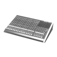
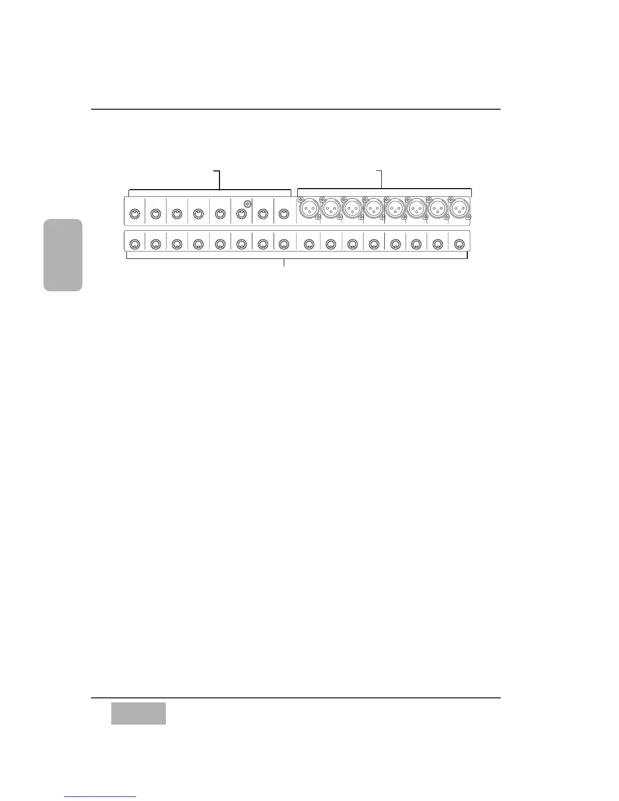
Rows 1 & 2 Connectors
Connectors in these two rows are numbered from right to left on the Rear
Panel.
INPUTS 1-8
These inputs are designed for XLR connectors. The input range is from -60dB
to +10dB, 5k Ω BAL. Use the MIC/LINE INPUT knobs on the Channel
Strips for adjustment of the incoming level. From the [CHANNEL] window,
the +48V phantom power can be individually turned on or off for each
channel via the screen.
INPUTS 9-16
Use these inputs with a 1/4” TRS (tip-ring-sleeve) phone plug connector. Use
the MIC/LINE INPUT knob to adjust the input level. The input range is from
-60dB to +10dB, 5k Ω BAL. There is no +48V phantom power. Microphones
used on these inputs must be externally powered if required.
INSERTS 1-16
These inserts are used for creating an effects loop. A 1/4” TRS phone plug,
with a level of +4 dB, 10k Ω UNBAL, provides an output (tip) send to effects, or
an input (ring) return from an outboard effects device.
Chapter 2
DA7 Users’ Guide
2
-
26
2
DA7 Tour
Inputs 9-16 (TRS). Use these for
balanced -60 to +10 signals
Inputs 1-8 (XLR). Use these for balanced
-60 to +10 signals. Phantom powered
Channel 1-16 Inserts. These are TRS send and return connectors.
Cutaway of DA7 Rear Panel (Rows 1 and 2) Input and Insert Connectors