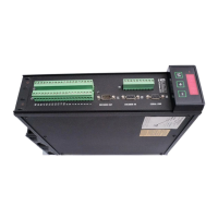
Certification for the Drive 10-5
650V AC Drive
Sensitive Equipment
The proximity of the source and victim circuit has a large effect on radiated coupling. The
electromagnetic fields produced by VSDs falls off rapidly with distance from the cabling/cubicle.
Remember that the radiated fields from EMC compliant drive systems are measured at least 10m
from the equipment, over the band 30-1000MHz. Any equipment placed closer than this will see
larger magnitude fields, especially when very close to the drive.
Do not place magnetic/electric field sensitive equipment within 0.25 metres of the following
parts of the VSD system:
• Variable Speed Drive (VSD)
• EMC output filters
• Input or output chokes/transformers
• The cable between VSD and motor (even when screened/armoured)
• Connections to external braking chopper and resistor (even when screened/armoured)
• AC/DC brushed motors (due to commutation)
• DC link connections (even when screened/armoured)
• Relays and contactors (even when suppressed)
From experience, the following equipment is particularly sensitive and requires careful
installation.
• Any transducers which produce low level analog outputs (<1V) , e.g. load cells, strain
gauges, thermocouples, piezoelectric transducers, anemometers, LVDTs
• Wide band width control inputs (>100Hz)
• AM radios (long and medium wave only)
• Video cameras and closed circuit TV
• Office personal computers
• Capacitive devices such as proximity sensors and level transducers
• Mains borne communication systems
• Equipment not suitable for operation in the intended EMC environment, i.e. with insufficient
immunity to new EMC standards
Doors
Metal
Work
110V
Control
24V Control
unscreened signals
STAR POINT
Incoming Safety Earth (PE)
Analogue Clean Earth
Dirty Earth
Digital Clean Earth
Signal/Control Screen
all screened signals not
Back Panel
U-clip used to terminate screen
connection to the back panel
PE = Protective Earth
0A = 0 Volts Analogue
0D = 0 Volts Digital
f = External Filter
VSD = Variable Speed Drive
PLC = Programmable Logic Controller
going directly to a VSD
Metal Work Earth
Back
Panel
PLC
PE
PE
PE
0D 0D
0D
0D
0A 0A
0A
to motor to motor to motor
screened screened
PE
VSD VSD
VSD
f
f
f
f
PE
PE
PE
Figure 10-2 Star Point Earthing

 Loading...


