An Overview of the Drive 2-1
650V AC Drive
Chapter 2 AN OVERVIEW OF THE DRIVE
Component Identification
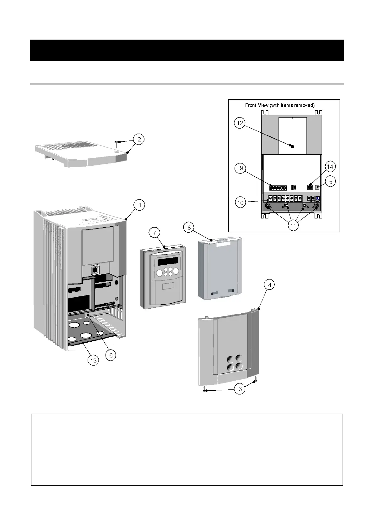
Figure 2-1 650V AC Drive, Frame C 11.0kW
1 Main drive assembly 8 Blank cover
2 Top cover (optional) 9 Control terminals
3 Terminal cover retaining screw 10 Power terminals
4 Terminal cover 11 Earthing points
5 RS232 programming port (P3) 12 Keypad port (P3)
6 Power terminal shield 13 Gland plate
7 6521 keypad (optional) 14 RS485 programming port (optional)
Through-panel fixing plate and screws not illustrated

 Loading...


