22
APEX615n Installation Guide
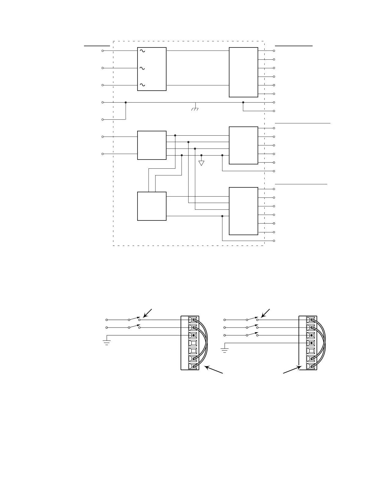
APEX6152 & APEX6154 Internal Connections
Motor Connector
Front Panel – Right Side
Front Panel – Left Side
AC Input
Connector
3 Phase
Rectifier
+
–
Low Voltage
Power
Supply
Controller
for
Power
Amplifier
V Bus +
Regen Resistor
V Bus –
Phase A
Phase B
Phase C
±15V
Tach Output
Gnd / Resolver Shield
ANA
GND
LEDs
Encoder Output
Resolver
Motor Ground
Shield
L1
L2
Earth
L3
Earth
3 – Phase
Power
Amplifier
Control L1
Control L2
DC-to-DC
Converter
6000
Controller
Iso +5V
+15V
–15V
Iso Ground
Triggers
Programmable I/O
Iso Gnd
+5V (isolated)
COM 1
COM 2
Limits
You must connect AC power to both L1/L2/L3 and Control L1/Control L2 (or to both L1/L2 and
Control L1/Control L2 on the APEX6151. The next drawing shows a simple way to do this.
L1
L2
L3
Earth
Earth
Control L1
Control L2
AC Power
Source
Disconnecting
Means
Disconnecting
Means
AC Input
Connector
Using insulated jumper wires:
• Connect L1 to Control L1
• Connect L2 to Control L2
L1
L2
Earth
Earth
Earth
Control L1
Control L2
AC Power
Source
AC Input
Connector
APEX6152 and APEX6154APEX6151
AC Connector with Jumpers Attached
Artisan Technology Group - Quality Instrumentation ... Guaranteed | (888) 88-SOURCE | www.artisantg.com

 Loading...


