K3.1.141e Manual NitroFlow HP_EN.doc - 12 -
3 Description of the appliance
3.1 General
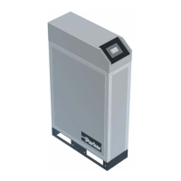
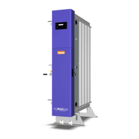
The NitroFlow
®
HP separates compressed air into nitrogen and an oxygen enriched
air stream. The separation system uses membranes. The compressed air is supplied
from a central system or from a dedicated compressor.
The nitrogen produced can be connected directly to the application or can be stored
in a nitrogen storage vessel. The NitroFlow
®
HP then switches on and off, depending
on the nitrogen demand. The NitroFlow
®
HP has a residual oxygen analyzer. This
analyzer continuously monitors the quality of the produced nitrogen.
3.2 Separation principle
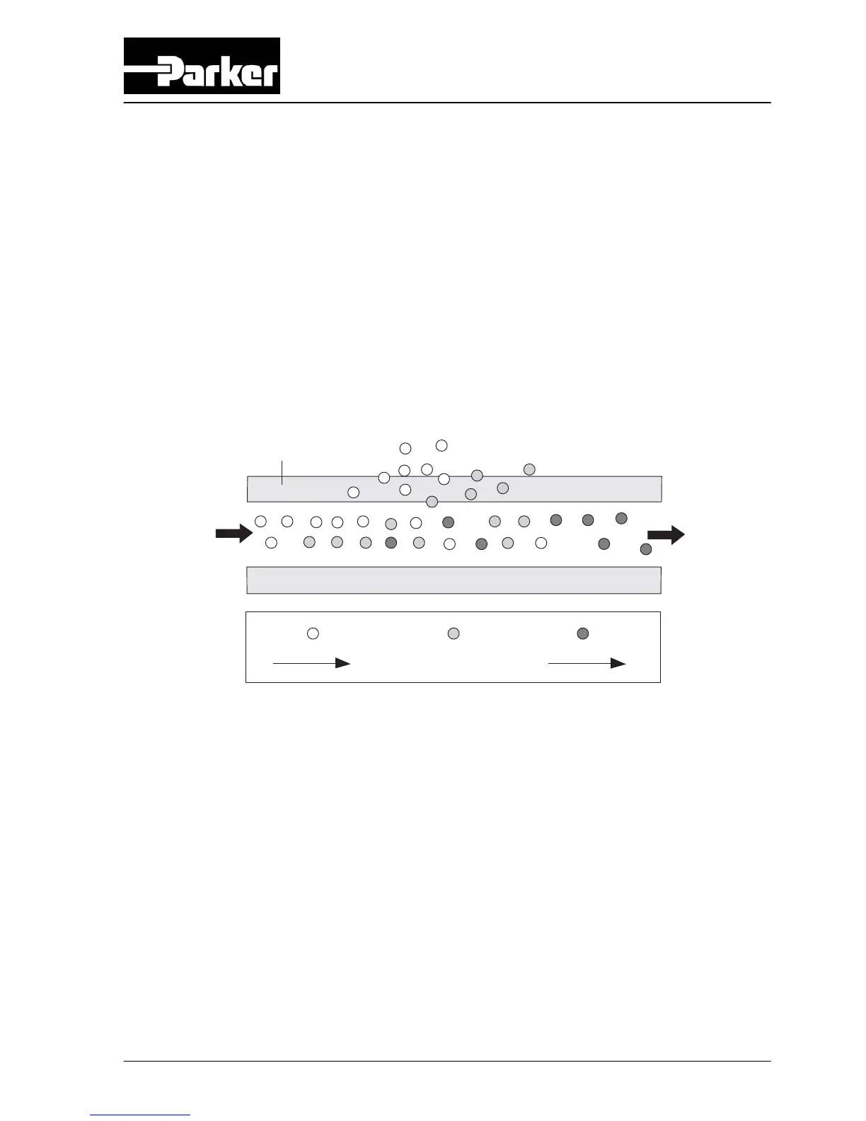
A
F
S
H2O - H2
O2
N2
B
C
Fig. 3-1: Separation principle
A Pressurized air inlet
B Hollow fibre membrane
C Nitrogen outlet
F Fast permeation
S Slow permeation
Ambient air contains nitrogen (78.1%), oxygen (20.9%), argon (1%), carbon dioxide,
water vapor and traces of other inert gasses. Pressurized air (A) is led through
hollow fibre membranes (B). The various air components diffuse through the porous
wall of the membranes.
The diffusion rate differs for the various gasses:
• Oxygen and water vapour have a high diffusion rate and diffuse rapidly through
the membrane wall.
• Nitrogen has a low diffusion rate and diffuses slowly through the membrane
wall. Nitrogen enriched air is released at the outlet of the membranes (C).
Pressurized nitrogen enriched air is released at the outlet of the membranes (E).
This air can be lead to a nitrogen storage vessel.