K3.1.141e Manual NitroFlow HP_EN.doc - 23 -
5.4 Unpack and check equipment
1. Open the packaging.
2. Make sure that all components have been delivered (refer to table 4-1).
5.5 Connecting to pressurized air supply
1. The NitroFlow
®
HP must be connected to the pressurized air
supply on the inlet indicated with the icon (fig. 5-1).
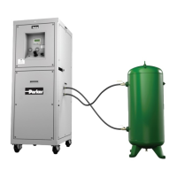
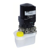
2. Lead the drain outlet (fig. 5-4) to receiving reservoir. The
amount of drained condensate collected in this reservoir
depends on the compressed air system. This may vary from
several liters a day to almost nothing.
CAUTION
Compressed air condensate can contain oil and other contaminants
and cannot be disposed to the sewer as such.
5.6 Connecting to mains electricity
Warning
Do not connect the NitroFlow
®
HP to the mains electricity with a wall
plug as to prevent incorrect disconnection.
1. The NitroFlow
®
HP must be connected to a fixed connection to mains.
2. Remove the cover above the inlet and outlet connections to connect the
NitroFlow
®
HP. It is not necessary to remove the top cover.
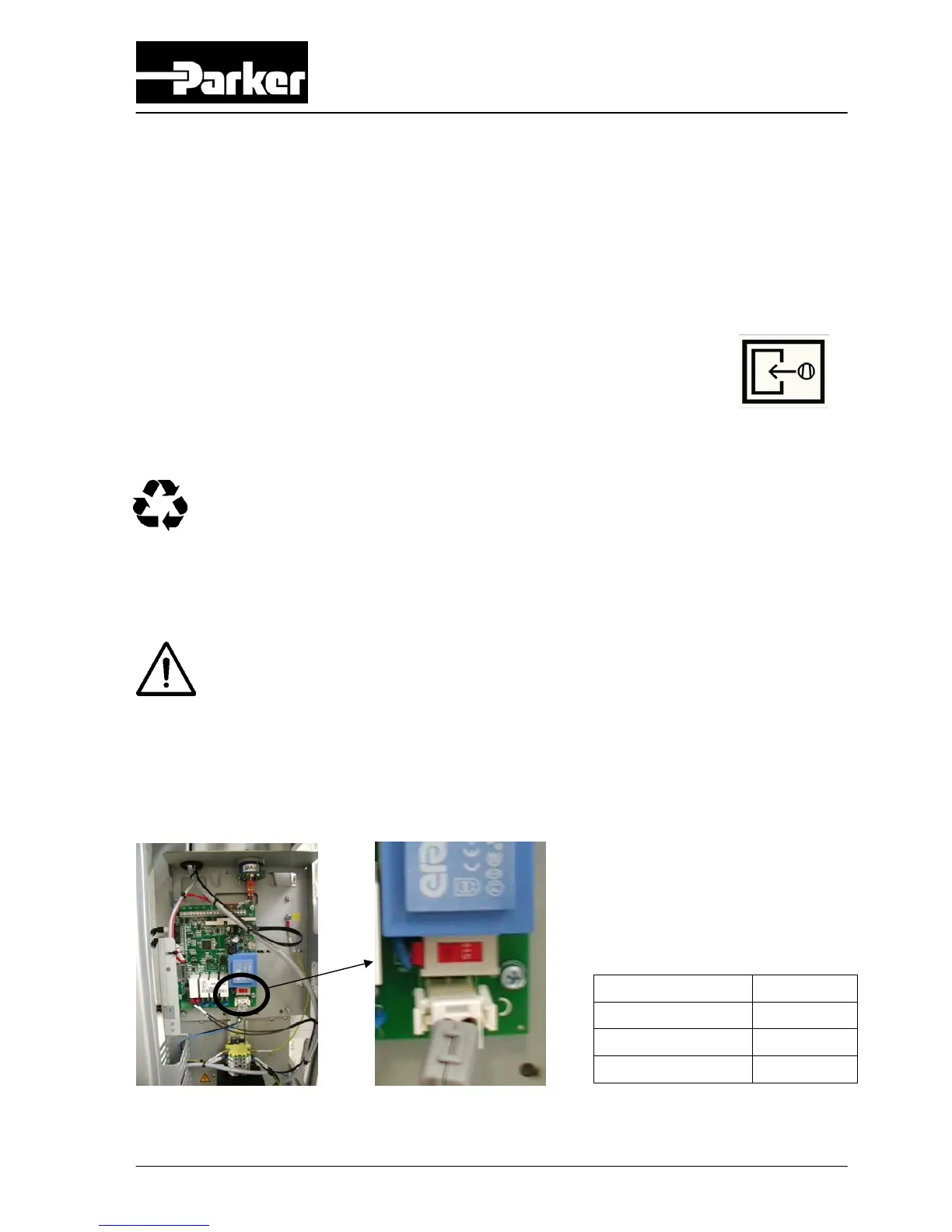
3. Select the right voltage with the voltage selector switch on the printed circuit
board (refer to fig 5-2).
Fig. 5-2 Voltage selector switch on printed circuit board Table 5-1: Switch position
4. Connect the unit to mains electricity (refer to fig. 5-3 and chapter 10).
Mains supply Position
100V – 50/60Hz 115V
115V – 50/60Hz 115V
230V – 50/60Hz 230V
Fig. 5-1
compressed
air inlet icon